CNK200 Cable-Nook
®
Interconnect Box
User’s Guide
400-0111-009
1
Welcome!
Everyone at Altinex greatly appreciates your CNK200 purchase.
We are confident you will find it to be reliable and easy to use. If
you need support, do not hesitate to call at 714-990-2300.
At Altinex, we are committed to developing unique and state of
the art Signal Management Solutions
®
for demanding audiovisual
installations. Welcome to the Altinex family of satisfied customers
around the world!
1. Precautions and Safety Warnings
Please read this manual carefully before using your CNK200
Cable-Nook Interconnect Box. Keep this manual handy for future
reference. These safety instructions are to ensure the long life of
your CNK200 and to prevent fire and shock hazards. Please read
them carefully and heed all warnings.
1.1 General
•
Qualified Altinex service personnel or their authorized
representatives must perform all service.
1.2 Installation
•
For best results, place the CNK200 Cable-Nook in a dry
area away from dust and moisture.
•
To prevent fire or shock, do not expose unit to water or
moisture. Do not place the CNK200 in direct sunlight, near
heaters or heat-radiating appliances, or near any liquid.
Exposure to direct sunlight, smoke, or steam can harm
internal components.
•
Handle carefully; dropping or jarring can damage the unit.
•
Never place fingers inside the openings in the back of the
unit as there are sharp edges inside.
•
Do not place heavy objects on top of the CNK200.
•
Install all cables according to the instructions.
1.3 Cleaning
•
Clean surfaces with a dry cloth. Never use strong
detergents or solvents such as alcohol or thinner. Do not
use a wet cloth or water to clean the unit.
1.4 FCC Notice
•
This device complies with Part 15 of the FCC Rules.
Operation is subject to the following two conditions: (1) This
device may not cause harmful interference, and (2) this
device must accept any interference received, including
interference that may cause undesired operation.
•
This equipment has been tested and found to comply with
the limits for a Class A digital device, pursuant to Part 15 of
the FCC Rules. These limits are designed to provide
reasonable protection against harmful interference when the
equipment is operated in a commercial environment. This
equipment generates, uses, and can radiate radio frequency
energy and if not installed and used in accordance with
instructions found herein, may cause harmful interference to
radio communications. Operation of this equipment in a
residential area is likely to cause harmful interference in
which case the user will be required to correct the
interference at his own expense.
•
Any changes or modifications to the unit not expressly
approved by Altinex
, Inc. could void the user’s authority to
operate the equipment.
2. Installation Procedures
Warning:
Altinex recommends using an experienced professional to make the table cutout. Before starting, go to the Altinex website
and download the latest cutout requirements, templates, and detailed installation instructions.
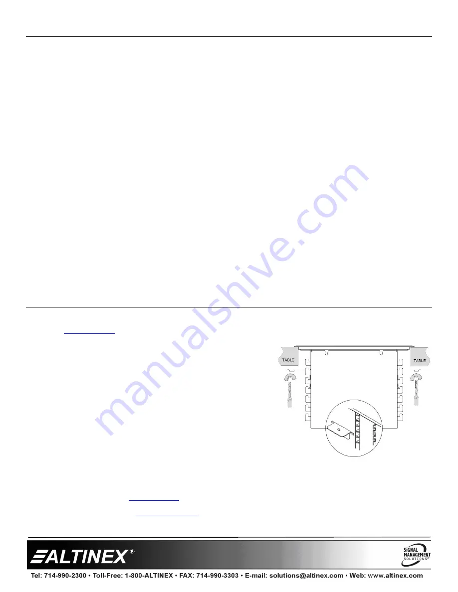
Step 1. Cut an opening into the table for the CNK200. Use the template and measurements provided on the Altinex website. The
CNK200 is designed to fit tabletops 0.5 - 3.5 in (13-89 mm) thick.
Step 2. Insert the CNK200 into the table cutout and secure it to the table using
the brackets and thumb screws provided.
Step 3. When using retaining brackets to hold cables, adjust the retaining
brackets close enough together to prevent the cables from falling, but
loose enough to be pulled up easily. The cables should be long enough
to be pulled up through the CNK and reach the equipment.
Preconfigured or customizable sectional plate cables need only be long
enough to mate with the cables/connectors on the plates.
Step 4. If desired, bundle like cables together using a protective sheath, meshed
sleeve, etc. Leave the free ends of the cables long enough for making
connections to the equipment on the table.
Step 5. Route cables through the bottom of the unit to the top. Use clamps provided to neatly route/secure cables to the bottom of the
table.
3. Limited Warranty/Return Policies
Please visit the Altinex website at
for details on warranty and return policies. In the case of a unit needing repair,
please complete a RMA (return material authorization) form located on the bottom left hand corner of the Altinex homepage. Once
completed, please email the form to


