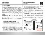
•
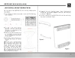
DEVICE CONNECTIONS AND BUTTONS
RESET:
To reset the device, take a small object like the end of a
paper clip and insert it into the RESET opening. To power cycle
the device, hold for less than
5
seconds. To reset to factory
default settings, hold for more than
5
seconds.
WARNING:
Resetting factory defaults will erase ALL settings that you have
made and will restore the device to factory default settings.
TEL:
Connects an analog telephone using an RJ11 cable.
ETHERNET 1-2:
Connects Ethernet-enabled devices such as
computers, gaming consoles or a wireless access point (router)
using RJ45 Ethernet cables.
USB:
Connects to USB devices.
PWR:
Connects to the supplied power adapter. Plug the other
end into the wall power outlet.
CABLE:
Connects to the cable wall outlet using a coaxial cable.
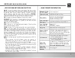
WPS:
On the front panel, the WPS button is used for the Wi-Fi
Protected Setup (WPS) push button method to connect a client
Wi-Fi device to the UBC1319AA00. When a user pushes the WPS
button or triggers WPS via the Web UI, it flashes for 4 minutes
until the WPS button is pushed on the wireless client device.
After a WiFi client attaches successfully, the LED remains on for
5 minutes, then turns o
ff
.
INFO:
On the front panel, the INFO button controls the LED ECO
Mode.
• When enabled, LED ECO Mode allows the modem to
automatically turn o
ff
the LEDs in order to conserve energy.
Note that the POWER LED will remain lit in ECO Mode.
• When pushed, the INFO button will disable the LED ECO Mode
for 30 seconds, and the LEDs will operate in the Normal State as
seen in the LED table on page 4.
• When the modem is in a faulty or alarm condition, LED ECO
Mode is automatically disabled. When the condition is resolved,
the device will again enable LED ECO Mode.
• By default, LED ECO Mode is automatically enabled 3 minutes
after powering up the modem.
•
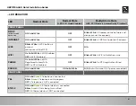
BASIC MODEM INFORMATION
3
UBC1319AA00 Quick Installation Guide
Example of Cable
RF MAC Address
00:71:CC:8E:54:C7
Firmware Version
UBC1319AA00-1xxx-v1.0.0rx
Compatibility
DOCSIS 3.0/2.0/1.0 certified
Ethernet 10/100/1000 Mbps
Wireless 802.11a/b/g/n/ac
Local Web Page
User Access
http://192.168.100.1
or
Local Web Page
Login (web UI)
Login:
MSO
Password:
changeme
Encryption
WPA2-PSK with AES encryption
Wireless Default
SSID
(wireless
network name)
“MyAltice” then a space, and the last 6
characters of the WAN MAC address (in
lower case). The SSID is the same for both
the 2.4 and 5GHz radio bands.
SSID Examples
2.4GHz radio with above MAC address:
SSID = MyAltice 8e54c7
5GHz radio with above MAC address:
SSID = MyAltice 8e54c7
WPA2-PSK
Wireless Key
Six digits (0-9) – in groupings of 2, 3 or 4
digits, two hyphens, and one name of a
color. It can be found on the device label.
This is your wireless password.
WPA2-PSK
Wireless Key
Example
5112-orange-91


