


Chapter 6: IP Core Interfaces
6–59
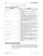
Physical Layer Interface Signals
June 2012
Altera Corporation
Stratix V Hard IP for PCI Express
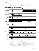
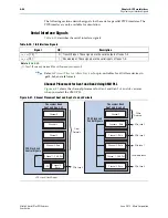
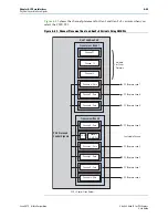
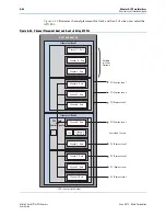
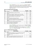
Channel Placement for Gen3 Using Both CMU and ATX PLLs
illustrates channel placement for Gen3 ×1 and ×4 variants using the ATX
PLL.
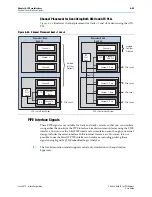
PIPE Interface Signals
These PIPE signals are available for Gen1 and Gen2 variants so that you can simulate
using either the one-bit or the PIPE interface. Simulation is much faster using the PIPE
interface. You can use the 8-bit PIPE interface for simulation even though your actual
design includes the serial interface to the internal transceivers. However, it is not
possible to use the Hard IP PIPE interface in hardware, including probing these
signals using SignalTap
®
II Embedded Logic Analyzer.
1
The Gen3 simulation model supports serial only simulation with equalization
bypassed.
Figure 6–46. Channel Placement Gen3 ×1 and ×4
T
r
ansceive
r
Bank
Gen3 x1
T
r
ansceive
r
Bank
LCD
LCD = Local Clock Divider
Channel 0 -
Data
Available
for Other
Protocols
Gen1, 2
Gen1, 2
Channel 2
Channel 4
Channel 5
Channel 3
Gen3 x4
Channel 0 - Data
Available
for Other
Protocols
Channel 2 - Data
Channel 1 - Data
Channel 5
Channel 3 - Data
Channel 4
CMU PLL
CCD
Channel 1
Data
CCD
CCD = Central Clock Divider
PCIe Lane 0
PCIe Lane 0
PCIe Lane 1
PCIe Lane 2
PCIe Lane 3
ATX
PLL0
Gen3
ATX
PLL1
Gen3