Altera Ethernet Blaster Communications Cable User Manual Download Page 34

Info–2

Chapter Info: Additional Information

Revision History

EthernetBlaster Communications Cable User Guide

© June 2008

Altera Corporation

Revision History

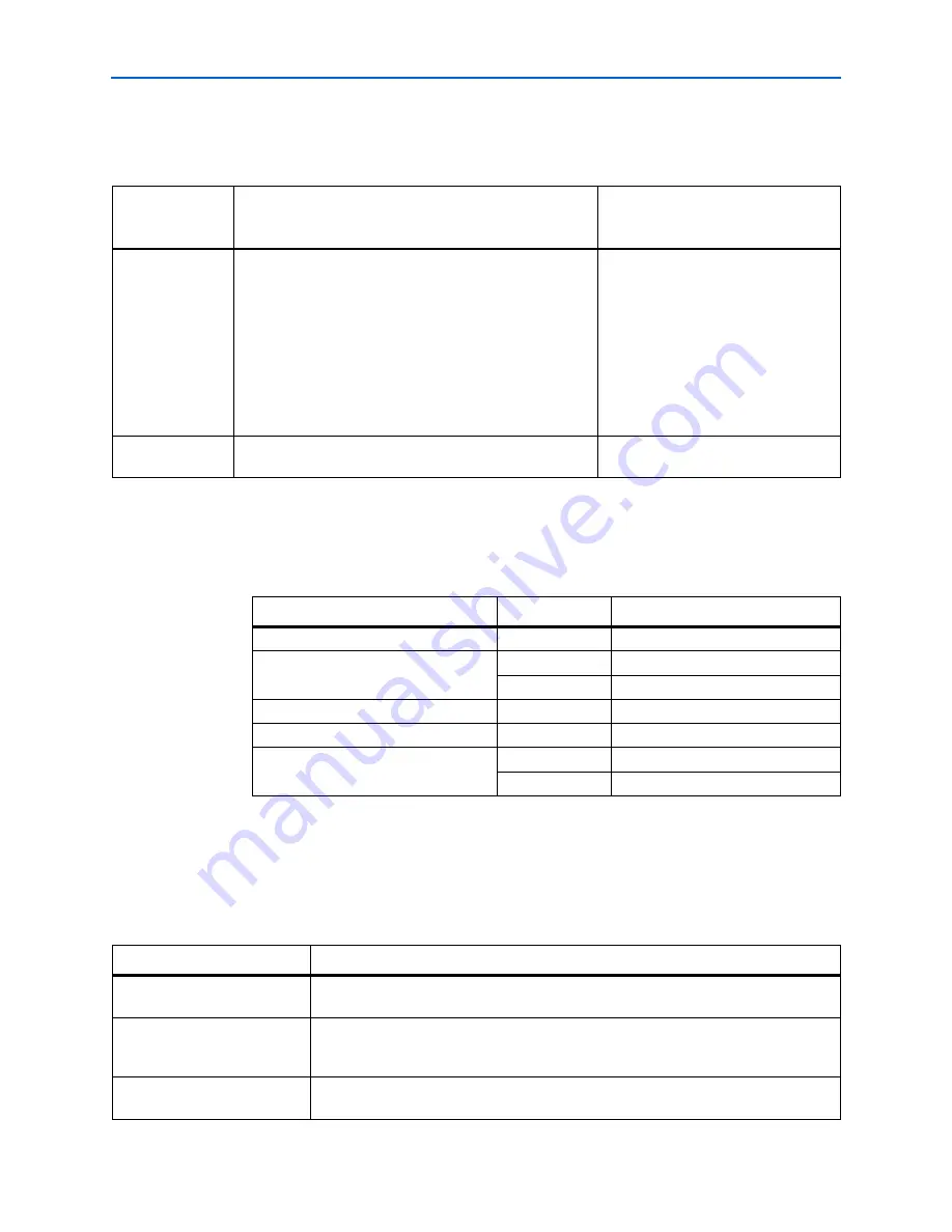
The table below displays the revision history for the chapters in this user guide.

How to Contact Altera

For the most up-to-date information about Altera® products, refer to the following 
table.

Typographic Conventions

This document uses the typographic conventions shown below.

Date and 

Document 

Version

Changes Made

Summary of Changes

July 2008, 
v1.1

Updates included:

Updated the style and format.

Created 

“Additional Information”

 page.

Updated 

Table 1–2

.

Updated 

Table 3–1

.

Updated Software Requirements

“Software 

Requirements”

 section.

Updated 

“Supported Devices”

 section.

December 2004, 
v1.0

Initial release.

Contact 

(1)

Contact Method

Address

Technical support

Website

www.altera.com/support

Technical training

Website

www.altera.com/training

Email

[email protected]

Product literature

Website

www.altera.com/literature

Altera literature services

Email

[email protected]

Non-technical support (General)

(Software Licensing)

Email

[email protected]

Email

[email protected]

Note to table:

(1) You can also contact your local Altera sales office or sales representative. 

Visual Cue

Meaning

Bold Type with Initial Capital 
Letters


Command names, dialog box titles, checkbox options, and dialog box options are shown 
in bold, initial capital letters. Example: 

Save As

 dialog box. 

bold type


External timing parameters, directory names, project names, disk drive names, filenames, 
filename extensions, and software utility names are shown in bold type. Examples: 

f

MAX

\qdesigns

 directory, 

d:

 drive, 

chiptrip.gdf

 file.

Italic Type with Initial Capital 
Letters


Document titles are shown in italic type with initial capital letters. Example: 

AN 75: High-

Speed Board Design.

Summary of Contents for Ethernet Blaster Communications Cable

Page 1: ...101 Innovation Drive San Jose CA 95134 www altera com EthernetBlaster Communications Cable User Guide Software Version 80 Document Version 1 1 Document Date July 2008...

Page 2: ...nts and pending ap plications maskwork rights and copyrights Altera warrants performance of its semiconductor products to current specifications in accordance with Altera s standard warranty but reser...

Page 3: ...etBlaster Hardware in the Quartus II Software 1 12 Removing the EthernetBlaster Hardware from the Quartus II Software 1 13 Chapter 2 EthernetBlaster Communications Cable Administration Introduction 2...

Page 4: ...iv EthernetBlaster Communications Cable User Guide July 2008 Altera Corporation...

Page 5: ...Direct Connection to a Computer Using a Crossover Cable 1 8 Figure 1 7 Direct Connection to a Computer Using a Standard Cable and a Crossover Adapter 1 9 Figure 1 8 EthernetBlaster Change Settings Pa...

Page 6: ...vi List of Figures EthernetBlaster Communications Cable User Guide July 2008 Altera Corporation...

Page 7: ...1 13 Table 2 1 Default Factory Settings 2 3 Table 3 1 EthernetBlaster VCC TRGT Pin Voltage Requirements 3 1 Table 3 2 EthernetBlaster Female Plug Signal Names Programming Modes 3 2 Table 3 3 EthernetB...

Page 8: ...viii List of Tables EthernetBlaster Communications Cable User Guide July 2008 Altera Corporation...

Page 9: ...ple users can remotely access Altera devices bringing a new level of productivity to prototyping and debugging Supported Devices You can use the EthernetBlaster communications cable to download config...

Page 10: ...Red Hat Enterprise Linux 4 Red Hat Enterprise Linux 5 HP UX version 11 0 or later Use the Quartus II software beginning with version 4 0 to configure your device The EthernetBlaster communications ca...

Page 11: ...an IP address is obtained and the cable is ready to use the status LED emits a steady green light If the attempt to obtain an IP address is unsuccessful the DHCP server may be down or absent the cabl...

Page 12: ...configuration or programming including the following setups Remote Connection via Network Using Default Factory Settings Direct Connection to a Computer Using Default Factory Settings Configuring the...

Page 13: ...Connection via Network Switch Router or Hub ETHERNET ETHERNET DC12V EthernetBlaster Communications Cable Ethernet Port Side View CAT 5 UTP Standard Cable Ethernet Jack CAT 5 UTP Standard Cable Etherne...

Page 14: ...on page 1 6 Browse to http host name and specify the host name from the label on the base of your EthernetBlaster communications cable The EthernetBlaster login window opens 1 Note that the last 4 dig...

Page 15: ...tBlaster communications cable including the current IP address See Figure 1 5 1 See Managing Passwords on page 2 1 to manage your password after initial login 10 Proceed to Setting Up the EthernetBlas...

Page 16: ...a Computer Using a Crossover Cable Computer ETHERNET ETHERNET DC12V EthernetBlaster Communications Cable Ethernet Port Side View CAT 5 UTP Crossover Cable Ethernet Jack Ethernet EIA TIA 568A Connecto...

Page 17: ...r contact your network administrator for instruction on how to change your IP address To maintain your computer s IP address and change the EthernetBlaster communications cable default IP address see...

Page 18: ...static IP addressing and complete your remote connection follow the directions below 1 Open the EthernetBlaster Status page 2 Click the Change Settings tab and select Static IP from the Connection Ty...

Page 19: ...or Direct Connection to a Computer Using Default Factory Settings on page 1 7 1 Open the EthernetBlaster Status page 2 Click the Change Settings tab and select DHCP from the Connection Type menu See F...

Page 20: ...s automatically populated with the EthernetBlaster communications cable detected on your subnet if Auto Detect is selected However if the cable is not on your subnet you must manually type the name or...

Page 21: ...remove Click Remove Server 1 See Setting Up the EthernetBlaster Hardware in the Quartus II Software on page 1 12 for instructions to add the EthernetBlaster communications cable back into the Quartus...

Page 22: ...1 14 Chapter 1 About the EthernetBlaster Communications Cable Cable Setup EthernetBlaster Communications Cable User Guide June 2008 Altera Corporation...

Page 23: ...control of settings and the ability to modify both the administrative password and the Quartus II remote connection password The Quartus II remote connection password enables clients to add the Ethern...

Page 24: ...en logging back into the administrative web page 1 The EthernetBlaster communications cable does not restart when the administrative password is reset Changing the Quartus II Remote Connection Passwor...

Page 25: ...nd the new password is effective Resetting the Hardware The EthernetBlaster communications cable reset button is located on the Ethernet port side of the hardware See Figure 2 3 Use a small pointed ob...

Page 26: ...tures better performance or bug fixes c Do not turn off the EthernetBlaster communications cable power when performing the firmware upgrade or severe damage will occur Firmware upgrades are included i...

Page 27: ...de 3 Click Browse and then locate and select the firmware file on your system Click Apply The EthernetBlaster communications cable restarts automatically after the firmware has been successfully upgra...

Page 28: ...2 6 Chapter 2 EthernetBlaster Communications Cable Administration Firmware Upgrade EthernetBlaster Communications Cable User Guide June 2008 Altera Corporation...

Page 29: ...equirements The EthernetBlaster VCC TARGET pin must be connected to a specific voltage for the device being programmed Connect pull up resistors to the same power supply as the EthernetBlaster VCC TAR...

Page 30: ...nding programming mode Figure 3 1 Ethernet Jack Pin Number Designations Pin Signal 1 2 3 4 5 6 7 8 TxData TxData RecvData RecvData 8 1 Figure 3 2 EthernetBlaseter 10 Pin Female Target Side Plug Dimens...

Page 31: ...ditions Table 3 3 through Table 3 5 summarize the maximum ratings recommended operating conditions and DC operating conditions for the cable 5 nCONFIG Configuration control nCONFIG Configuration contr...

Page 32: ...r Cable DC Operating Conditions Symbol Parameter Conditions Min Max Unit VIH High level input voltage VCC TARGET or 3 3 V VCC TARGET 0 2 V High level input voltage VCC TARGET 3 3 V 3 1 V VIL Low level...

Page 33: ...pter in volume 1 of the MAX II Device Handbook Serial Configuration Devices Data Sheet Programming Configuration chapter in the Introduction to Quartus II manual The Programming module of the Quartus...

Page 34: ...support Website www altera com support Technical training Website www altera com training Email custrain altera com Product literature Website www altera com literature Altera literature services Emai...

Page 35: ...yped exactly as it displays is shown in Courier type For example c qdesigns tutorial chiptrip gdf Also sections of an actual file such as a Report File references to parts of files for example the AHD...

Reviews: