Instruction manual 91/121 V6.3
Installation
•
Mounting noise suppressors (snubber for a.c. or diodes for d.c.) parallel to the coils of all contactors, relays, solenoid valves,
single-phase motors, three-phase motors, etc.
4.2 Motor cable
Only use shielded cable with 3 cond earth for powering the motor and twisted shielded cable in pairs for the transducer
(ALTER model
CAV16PSCH-SP1
).
The conductors section of power cables is shown in table 2 on page 7.
Connect the shield of the power and signal cables to the case of the drive and motor.
The connection of the shield to the case shall be as short as possible (maximum length 100 mm). The uncovered part of the cable shall
not exceed 50 mm.
It is recommended to use shielded cables without joints. If this is impossible, use:
•
For signals: shielded connectors that do not interrupt the screen
•
For power: shielded connectors or terminal blocks.
If a terminal block is used, the uncovered (unshielded) part of the cable must be minimised and the screens of the two cables must be
connected to a (non-insulated) ground terminal.
Using the following formula, calculate the value of the “electric time constant” of the motor; If the result is less than 10msec, an in-
ductance between the motor and the drive shall be mounted. In case of doubt or for further information, please contact the ALTER
Technical Office.
T
e
=
L
mot
R
mot
T
e
=
Electric time constant [msec].
L
mot
= Inductance of the motor (see motor technical specifications) [mH].
R
mot
= Resistance of the motor (see technical specifications of the motor).
For the sizing of the components drawn in Drawing 1 on page 11 and in Drawing 2 on page 12, see table 2 on page 7.
Connect the thermal probe as indicated in Drawing 1 on page 11 or Drawing 2 on page 12 only if the signal is not available on the
transducer connector.
4.3 Power connections
To identify the location of the connectors on the drive, see Drawing 24 on page 78 and Drawing Drawing 25 on page 79.
4.3.1 Three-phase or single-phase network (only for PWM3D-001)
The three-phase power supply network shall be connected to the L1
,
L2
,
L3 terminals
available
on the X1 connector in the case of a
size 1 drive or on a screw terminal in the case of a drive size 2.
Only for
drives size 1
it is possible to supply them with
single-phase
voltage: In this case, use only the
L1
and
L2
terminals.
NOTE:
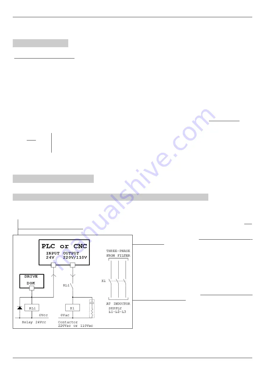
The contacts of the contactor mounted on the power supply line (as indicated in Drawing 1 on page 11) can be closed only
if the DOK output is active at +24V; in the event that the DOK output go to 0V (in case of alarm for example) the switch must be
opened immediately.
Drawing 3
The diagram next to it illustrates the correct connection of the con-
tactor coil control that dissects the power supply to the drive.
The digital output “DOK” of the drive controls the coil of a 24Vcc
relay (RL1) and the same signal goes to the PLC or CNC to signal
if the drive goes to FAULT.
The auxiliary contact of the RL1 relay is serialised to the coil of
the power contactor (K1) which is controlled by the CNC or PLC
whenever it wishes.
In the case that the drive goes into alarm or in case of lack of
power to the auxiliary services, thus making the contactor off and
the power supply on the L1, L2, L3 is removed even if the CNC
tries to drive the K1 contactor.
This ensures the correct management logic of the contactor.
Alter Elettronica s.r.l.
13


