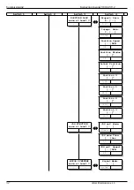
Commissioning
Instruction manual 91/104 V9.2
Motor torque
Indicates the percentage value of the torque delivered by the motor. Remember that the nominal torque can only be delivered up to the
rated speed; beyond that point the torque decreases due to field weakening of the motor.
DC Bus Voltage
Indicates the voltage in Volt of the DC BUS inside the drive. This value depends on the three-phase supply voltage (if powered on ter -
minals L1, L2, L3) and can be calculated using the following formula:
V
BUS
=
V
LINE
⋅
√
2
V
LINE
= Power supply voltage on L1, L2, L3 (Vac)
V
BUS
=
DC BUS voltage (on DC+ and DC- terminals) (Vdc)
Heat Sink Temp
Indicates the temperature in degrees centigrade of the heat sink inside the drive. This temperature must be below 75 °C otherwise the
drive goes in block indicating the anomaly on the display. If the temperature tends to be too high, the causes may be due to lack of
ventilation.
Capacitor Temp
Indicates the temperature in degrees centigrade of the capacitors inside the drive. This temperature must be below 60 °C otherwise the
drive goes in stop indicating the anomaly on the display. If the temperature tends to be too high, the causes may be due to the lack of
ventilation or the need to mount an additional set of external capacitors due to the type of use done with the drive (ALTER module
13/007).
DSP Temp
Indicates the temperature in degrees centigrade of the DSP that controls the drive. This temperature must be below 70 °C otherwise
the component can be damaged. In case of higher temperature, contact the ALTER Technical Office.
Transducer board
Menu group grouping some parameters to control the optional transducer card type and the status of the connected transducer.
Transducer board for
Indicates the type of transducer that can be connected to the X14 connector.
Firmware version major
Larger version number of the optional transducer card that is installed inside the drive.
Firmware version minor
Minor version number of the optional transducer card that is installed inside the drive.
Resolver signal
Indicates the status of the voltage signal coming from the connected resolver on X14. The available statuses are:
•
LOW: The resolver’s signal is low. Rotate the trimmer next to the X14 connector in the hourly direction.
•
OK: The resolver’s signal is correct.
•
HIGH: The resolver’s signal is high. Rotate the trimmer next to the X14 connector in the anticlockwise direction.
SinCos signal A and B
Indicates the status of the voltage signal coming from SinCos or EnDat connected to X14 pin 3-4-6-7. The available statuses are:
•
LOW: The transducer signal is low. The cable or wires could be interrupted or short-circuited.
•
OK: The transducer signal is correct.
•
HIGH: The transducer signal is high. The transducer may not be compatible or the connections are wrong.
SinCos signal C and D
Indicates the state of the voltage signal coming from SinCos connected to X14 pin 19-20-21-22. The available statuses are:
•
LOW: The transducer signal is low. The cable or wires could be interrupted or short-circuited.
•
OK: The transducer signal is correct.
•
HIGH: The transducer signal is high. The transducer may not be compatible or the connections are wrong.
Man Offset Calc
This menu appears only with the optional boards for SinCos (01/325), phonic Wheel (01/326), EnDat (01/327).
With the drive disabled (Led RUN off) you can change the parameter in ENABLED, to activate the calibration function automatically
the offset of the incremental sinusoidal signal of the encoder.
For the calibration procedure, see the explanation of paragraph "5.5.5“ on page 65.
Serial comm. status
Indicates the status of the serial connection of the EnDat encoder connected to X14 pin 9-10-11-12. The available statuses are:
46
Alter Elettronica s.r.l.

