background image


23 

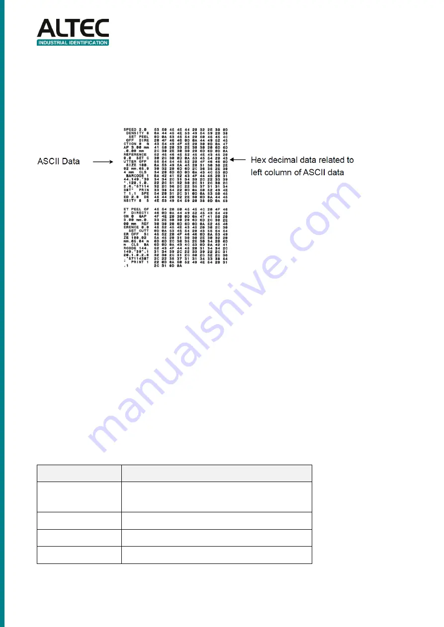
Dump mode 

Printer will enter dump mode after printing printer configuration. In the dump mode, all characters will be 
printed in 2 columns as following. The left side characters are received from your system and right side 
data are the corresponding hexadecimal value of the characters. It allows users or engineers to verify and 
debug the program. 


Note: 
1. 

Dump mode requires 2” wide paper width. 

2.  Turn off / on the power to resume printer for normal printing. 
3.  Press FEED button to back to the previous menu. 

4.3.3  Printer Initialization 

Printer initialization is used to clear DRAM and restore printer settings to defaults. 
Printer initialization is activated by the following procedures. 
1.  Turn off the power switch. 
2.  Hold on the button then turn on the power switch. 
3.  Release the button when LED turns green after 5 amber blinks. (Any green will do during the 5 blinks). 


The LED color will be changed as following: 
Amber 

 red (5 blinks) 

 amber (5 blinks) 

 green (5 blinks) 

 green/amber (5 blinks) 


red/amber (5 blinks) 

 solid green 

 
Printer configuration will be restore to defaults as below after initialization. 
 

Parameter 

Default setting 

Speed 

127 mm/sec (5 ips) (203DPI) 
76.2 mm/sec (3 ips) (300DPI) 

Density 

Label Width 

2” (50.8 mm) 

Label Height 

2” (50.8 mm) 

Summary of Contents for ATP-23

Page 1: ...ATP 23 THERMAL TRANSFER DIRECT THERMAL LABEL PRINTER USER S MANUAL...

Page 2: ...ng Ethernet by Diagnostic Utility Option 15 3 4 1 Using USB interface to setup Ethernet interface 15 3 4 2 Using Ethernet interface to setup Ethernet interface 15 4 LED and Button Functions 18 4 1 LED...

Page 3: ...ability You will enjoy trouble free high throughput for printing labels with this printer 1 2 Compliances CE Class B EN55022 1998 A1 2000 A2 2003 EN55024 1998 A1 2001 A2 2003 IEC 61000 4 Series EN6100...

Page 4: ...Please retain the packaging materials in case you need to reship the printer Unpacking the printer the following items are included in the carton One printer unit One Windows labeling software Window...

Page 5: ...5 2 2 Printer Overview 2 2 1 Front View 1 LCD display Factory option 2 LED indicator 3 Feed button 4 Paper exit chute 5 Media view window 6 Top cover open lever...

Page 6: ...bbon rewind hub 3 Ribbon rewind gear 4 Print head 5 Ribbon supply hub 6 Gap sensor receiver 7 Media holders 8 Media guide 9 Top cover support 10 Black mark sensor 11 Platen roller 12 Gap sensor transm...

Page 7: ...face availability Recommended MicroSD card specification SD card spec SD card capacity Approved SD card manufacturer V1 0 V1 1 MicroSD 128 MB Transcend Panasonic V1 0 V1 1 MicroSD 256 MB Transcend Pan...

Page 8: ...the rear of the printer and then plug the power cord into a properly grounded power outlet Note Please switch OFF printer power switch prior to plug in the power cord to printer power jack 3 2 Loadin...

Page 9: ...media sensor and place the label leading edge onto the platen roller 4 Move the media guides to fit the label width by turning the media guide adjuster knob 5 Hold the top cover and press the top cove...

Page 10: ...ate the gap black mark sensor when changing media 3 2 2 Loading Media in Peel off Mode Option 1 Refer to section 3 2 1 to load the media 2 Open the top cover and peel off panel after calibrated the se...

Page 11: ...rk sensor when changing media 3 2 3 Loading Media in Cutter Mode Option 1 Refer to section 3 2 1 to load the media 2 Lead the media through the cutter paper opening 3 Close the top cover gently 4 Use...

Page 12: ...Loading the Thick Media Thickness is 0 19 mm 1 Open the printer top cover by pulling the tabs located on each side towards the front of the printer and then lift the top cover to the maximum open angl...

Page 13: ...e printer and lifting the top cover to the maximum open angle 2 Insert the ribbon right side onto the supply hub Align the notches on the left side and mount onto the spokes 3 Open the ribbon access c...

Page 14: ...head 6 Stick the ribbon onto the ribbon rewind paper core 7 Turn the ribbon rewind gear until the ribbon plastic leader is thoroughly wound and the black section of the ribbon covers the print head C...

Page 15: ...r firmware V6 00 and later versions 4 The Diagnostic Utility default interface setting is USB interface If USB interface is connected with printer no other settings need to be changed in the interface...

Page 16: ...t IP address will be shown in the right side IP address Printer Name field 7 Click Change IP Address to configure the IP address obtained by DHCP or static The default IP address is obtained by DHCP T...

Page 17: ...p and go back to Diagnostic Tool main screen Factory Default button This function will reset the IP subnet mask gateway parameters obtained by DHCP and reset the printer name Web setup button Except t...

Page 18: ...cutter error Red Flash This illuminates a printing error such as head open paper empty paper jam or memory error etc 4 2 Regular Button Function 1 Feed labels When the printer is ready press the butto...

Page 19: ...ower switch 3 Release the button when LED becomes red and blinking Any red will do during the 5 blinks It will calibrate the gap black mark sensor sensitivity The LED color will be changed as followin...

Page 20: ...e power switch 2 Hold on the button then turn on the power switch 3 Release the button when LED becomes amber and blinking Any amber will do during the 5 blinks The LED color will be changed as follow...

Page 21: ...er will print the printer configuration after gap black mark sensor calibration Self test printout can be used to check if there is any dot damage on the heater element printer configurations and avai...

Page 22: ...22...

Page 23: ...inter Initialization Printer initialization is used to clear DRAM and restore printer settings to defaults Printer initialization is activated by the following procedures 1 Turn off the power switch 2...

Page 24: ...old on the button then turn on the power switch 3 Release the button when LED turns green amber after 5 green blinks Any green amber will do during the 5 blinks The LED color will be changed as follow...

Page 25: ...hout running the program by the power on utility Please follow the procedures below to skip an AUTO BAS program Turn off printer power Press the FEED button and then turn on power 3 Release the FEED b...

Page 26: ...solutions have been invoked please contact us 5 1 LED Status This section lists the common problems that according to the LED status and other problems you may encounter when operating the printer Al...

Page 27: ...27 5 2 Print Problem...

Page 28: ...inter 1 Please use one of following material to clean the printer Cotton swab Head cleaner pen Lint free cloth Vacuum Blower brush 100 ethanol 2 The cleaning process is described as following Note Do...

Page 29: ...d extend printer life The maximum printing ratio per dot line is 15 for this printer To print the full web black line the maximum black line height is limited to 40 dots which is 5mm for 203 DPI resol...

Reviews: