2
INTRODUCTION
Thank you for having purchased the uninterruptible power supply
AL02 ECO
of the trademark
ALTEC
.
With the latest technological innovations, this product offers all the necessary protections against
the short circuits, the overvoltage and the overcurrent.
The auto-protected housing against opening and removal can have lead batteries type 12V-7Ah or
12V-2Ah.
Its output voltage is regulated to 13,7V and its output current can reach 2A without battery backup.
The charge current of the battery is electronically limited to 250mA. With this circuit, when the
battery is charging, the output of the AL02 ECO can still deliver up to 1.75A.
In case of prolonged power failure, the AL02 ECO has a deep discharge detection that cuts
the battery when the voltage across its terminals falls below 9VDC.
Two outputs type transistor with open collector (ERR OUT) indicate the power failure (Ac in) and
the low battery (batt) (below 12V), to complete the green light on the front that indicates the
presence of the sector voltage and the red light that indicates a failure of the battery.
SAFETY INSTRUCTIONS
•
All work on the AL02 ECO must be performed by qualified or correctly trained for
the safety procedures.
•
Provide, for the installation of the electrical wiring of the building, a switching device
that can be quickly accessible near the AL02 ECO.
•
Before any work on the AL02 ECO, disconnect the sector (230VAC).
•
Do not block, cover the housing openings and do not insert objects into the slots.
•
Do not try to repair the AL02 ECO yourself.
•
Avoid any intervention on your AL02 ECO during stormy weather.
•
Use only the battery types that are listed in the table of characteristics.
•
Take the necessary precautions to avoid any risk of electrostatic discharge during
the installation or maintenance of the AL02 ECO.
INSTALLATION
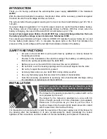
AL02 ECO is only for an indoor use. It is fixed in a vertical
and flat surface larger than its housing, leaving at least 5
cm on each side.
The tamper for the opening is provided by a slide switch on the
card, powered by the cover.
The tamper for the removal is provided by a screw with 60-
70mm of length and with 4 to 5mm of diameter (not supplied).
Please see on the picture as you have to put the screw. It
must be screwed into the wall until its head comes into contact
with the electronic circuit without forcing.
It is imperative to do some tests to verify the operation of the power supply and of the tamper for
the opening after the installation. It is also recommended to check periodically the correct
tightness of the connections and the condition of the internal battery and replace it if necessary.


