background image

19

WARNING

It is dangerous and illegal for the driver to watch the TV/Video while
driving the vehicle. The driver may be distracted from looking ahead
and an accident could occur.

!

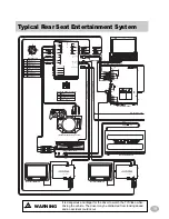
 Typical Rear Seat Entertainment System

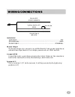
Red - Accessory (+12v)

Black - Ground

Whit

e

/B

ro
w

n

 - 

IR Re

m

o

te 

O

u

tp
u

t 2

Whit

e

/B

ro
w

n

 - 

IR Re

m

o

te 

O

u

tp
u

t 1

Whit

e

/B

ro
w

n

 - 

IR Re

m

o

te 

In

p

u

t

White/Brown - IR Remote Output 1 

§

(Optional CHA-S624)

(Optional TME-M750)

(Optional TME-M750)

(Optional DVA-5205)

(Optional Video Game Console)

Male DIN Cable

1

2

3

4

5

6

7

8

9

5

RCA Audio Ground (-)

6

IR Code

7

A/V Switch (-)

8

1

RCA Video (+)

2

RCA Video (-)

3

RCA Right (+)

4

RCA Left (+)

9

Shell Ground

Ignition / Accessory

1

Empty

2

Red - Accessory

3

Brown/White - IR Remote

4

Black - Ground

Front View Power Connector

1

2

3

4

(Optional IVA-C800)

DVD

/////ALPINE

MULTI-ZONE AV CONTROLLER / TV TUNER   TCS-V430A

VIDEO

L

R

AUX IN

DIVERSITY ANTENNA

1

2

3

4

VCR

MONITOR 2

MONITOR 3

VIDEO

L

AUDIO

MONITOR 1

REMOTE 2

POWER SUPPLY

VIDEO

L

R

R

E

S

E

T

REMOTE 3

WIDE  COLOR  LCD  MONITOR

POWER

VOLUME

DN

UP

SELECT

TME-M750

TV TUNER INPUT

PHONE OUTPUT

VIDEO

L

R

AUDIO

MOBILE COLOR MONITOR

TME-M750

NAVIGATION INPUT

DISPLAY OUTPUT

POWER SUPPLY

VIDEO

L

R

AUDIO

AUX 2

V I D E O

AUX2

AUX

1

R

L (MONO)

AU DI O

AUX  I NPUT

VID EO

AUX  OUTPUT

NA VI GA TI ON  I NPUT

40W X4  A M PL I FI ER

R

FM  A NTENN A

REMO TE OUT

POW ER SUPPL Y

DI SPL A Y  OUTPUT

A i- NET

L (MONO)

AU DI O

VID EO

R

L

FRON T

REA R

AU DI O

SUB W .

CONN ECTI ON S

1 6 1 5 1 4 1 3 1 2 11 1 0 9

8

1 Red

( Roug e )

Sw i tch ed  Po w e r
( I g n i t i o n ) L e a d

2 Pi n k/ Bl a c k ( Ro se / No i r )

A u d i o  I n t e rr u p t
i n  L e a d

4 Gr a y

( Gr i s)

Fr o n t  SP ( R)  +

5 Gr a y / Bl a c k ( Gr i s/ No i r )

Fr o n t  SP ( R)  —

6 W h i t e

( Bl an c )

Fr o n t  SP (L)  +

7 W h i t e / Bl a c k( Bl an c / No i r )

Fr o n t  SP (L)  —

8 Bl a c k

(N o i r )

Gr ou n d  L e a d

9 Bl u e

( Bl e u )

Po w e r  A n t e nna
L e a d

1 0 Bl u e / W h i t e ( Bl e u / Bl an c )

Re m o t e  Tu r n - On
L e a d

11 Y e ll o w / Bl u e( Ja u n e / Bl e u )

Pa r k i n g - Br a k e

1 2 Vi o l e t

( Vi o l e t )

Re a r  SP ( R)  +

1 3 Vi o l e t / Bl a c k( Vi o l e t / No i r )

Re a r  SP ( R)  —

1 4 Gr ee n

( Ve rt )

Re a r  SP (L)  +

1 5 Gr ee n / Bl a c k(Ve rt / No i r )

Re a r  SP (L)  —

1 6 Y e ll o w

•  Fo r  de t a i l ed  e x p l ana t i o n s, r e f e r  t o  th e  GUID E FOR
  I NSTA LL A TI ON  A ND CONN ECTI ON S.
•  Fu r  na h a r e  Er k a r u n g e n , si e h e  i n  de r  A NL EI TUNG
  FUR EI NBAU  UND A NSCHL USSE.
•  Pou r  e x p l i c a t i o n  de s de t a i l s, se  r e p o rt e r  a u  GUID E
  POUR I NSTA LL A TI ON  ET CONN EXI ON S.
•  Pe r  l a  sp i e g a zi o n e  de i  de tt a g l i , c o n su l t a r e  l a  GUI -
  DA  PER L  I NSTA LL A ZI ON E E I  COLL EGA M ENTI

•  Se  I NSTA LL A TI ON S OCH A NSL UTNI NGSA NVI SI N-
  I NGA RNA  f o r  na r m a r e  an v i sn i n g a r .

( Ja u n e )

Ba tt e r y  L e a d

3

7

6

5

4

3

2

1

4

3

2

1

CONN ECTOR

CONN ECTOR

Co nn e ct o r

Pi n  NO .

Co l o r

Co nn e ct i o n

1 W h i t e / Br o w n

( Bl an c / Br u n )

Re m o t e  Ou t  AUX 1

2 W h i t e / Br o w n

( Bl an c / Br u n )

Re m o t e  Ou t  AUX2

4 Y e ll o w / Bl a c k

( Ja u n e / No i r )

Foo t  Br a k e

3

Co nn e ct o r

Pi n  NO .

Co l o r

Co nn e ct i o n

SP

SP

R

WIDE  COLOR  LCD  MONITOR

POWER

VOLUME

DN

UP

SELECT

TME-M750

TV TUNER INPUT

PHONE OUTPUT

VIDEO

L

R

AUDIO

MOBILE COLOR MONITOR

TME-M750

NAVIGATION INPUT

DISPLAY OUTPUT

POWER SUPPLY

VIDEO

L

R

AUDIO

AUX 2

AUDIO

AUDIO

Summary of Contents for TCS-V430A

Page 1: ...TCS V430A Multi Zone AV Controller TV Tuner OWNER S MANUAL...

Page 2: ...ecautions may result in fire DO NOT USE NUTS OR BOLTS IN THE BRAKE SYSTEM FOR INSTALLATION OR GROUND CONNECTIONS Never use safety related parts such as bolts or nuts in the steering or brake systems o...

Page 3: ...ons for shorted circuitry Also have your vehicle s voltage regulator checked Maintenance If you have problems do not attempt to repair the unit yourself Return it to your Alpine dealer or the nearest...

Page 4: ...V input including internal TV tuner Infrared wireless remote control On Sscreen display OSD for each monitor output Last status memory Multiple IR Remote IN for connection to Alpine products having re...

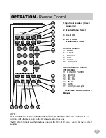
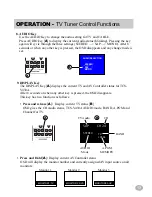
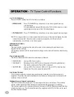
Page 5: ...n the RUE 4150 remote control for the overhead monitors 1 Input Source Select Direct Sequential 2 Monitor Output Select 3 Direct CH 4 AUTO CH A Manual SEEK CH B TV Tuner Controls 5 BAND 6 A PGM 7 PRES...

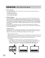
Page 6: ...y displaying the TV video 2 The Monitor connected to the the 2ND output will display MONITOR 2 TV 3 Before its OSD turns off Press any of the SOURCE keys B DVD VCR AUX to change from TV to the desired...

Page 7: ...34567890123456789012 A 12345678901234567890123456789012 12345678901234567890123456789012 12345678901234567890123456789012 12345678901234567890123456789012 12345678901234567890123456789012 123456789012...

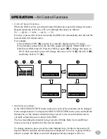
Page 8: ...utput If the 3RD Monitor Output is pressed A the MONITOR3 line in the menu will blink Change the source for this monitor as previously described Either Direct Source or Cyclic selection is available f...

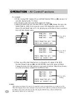
Page 9: ...urce only To select another source use the AUTO CH buttons A to move up or down in the menu In addition pressing any of the AV SOURCE buttons will activate its corresponding source directly For exampl...

Page 10: ...sired channel appears immediately and the OSD disappears in about 3 seconds When you enter less than three digits it will change to the desired channel after 3 seconds delay and the OSD disappears in...

Page 11: ...can receive up to 125 channels 1 125 The total number of channels available for both TV and Cable TV is 181 after subtracting the redundant 12 channels 2 through 13 6 AUTO PROGRAM A PGM Key AUTO PROGR...

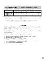
Page 12: ...list Pressing and releasing the PRESET key A will list all the PRESETs and their assigned channels B Pressing one of the numeric keys while the OSD is displayed changes the channel to the one corresp...

Page 13: ...7890123456789012345 1234567890123456789012345 1234567890123456789012345 1234567890123456789012345 1234567890123456789012345 1234567890123456789012345 1234567890123456789012345 123456789012345678901234...

Page 14: ...the unit will return to their factory defaults Power Indicator LED The Power Indicator LED shows the unit status as follows POWER ON Always ON Unit is active STAND BY Blinking Unit is OFF but receivi...

Page 15: ...ation and more This product utilizes a 4 Channel diversity antenna system designed especially for in car use Some performance increase may be realized by upgrading the antenna from any other third par...

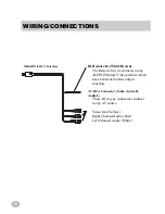
Page 16: ...E Mobile Video product which has an external remote output function AV RCA Connector Video Audio R Audio L These RCA type connectors connect to any AV source Video Out Yellow Right Channel Audio Red L...

Page 17: ...t function For example products such as a DVD and VCR Ground GND Connect this lead to a good chassis ground on the vehicle Make sure the connection is made to bare metal and is securely fastened using...

Page 18: ...g RCA s and mounting flange 202 x 158 x 35 mm 7 95 x 6 22 x 1 38 in Weight 720 g 1 59 lb Wireless remote control Power Source DC 3V AAA battery x 2 Remote control range about 2m 6 5 feet within 30 deg...

Page 19: ...oug e Sw itch ed Po w e r Ig n it io n L e ad 2 Pin k Black Ro se No ir Au d io In t e rr u p t in Le ad 4 Gr ay Gr is Fr o n t SP R 5 Gr ay Black Gr is No ir Fr o n t SP R 6 W h it e Blan c Fr o n t...

Page 20: ......

Page 21: ...s Boulevarde Keysborough Victoria 3173 Australia Tel 03 9769 0000 ALPINE ELECTRONICS GmbH Kreuzerkamp 7 11 40878 Ratingen Germany Tel 02102 45 50 ALPINE ITALIA S p A Via C Colombo 8 20090 Trezzano Sul...

Reviews: