


11
010-353-B9-001 Rev. A1 (09/2015)
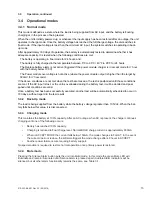
2.0
Installation, continued
2.1 Installation and connection,
continued
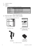
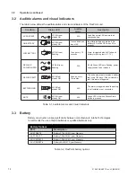
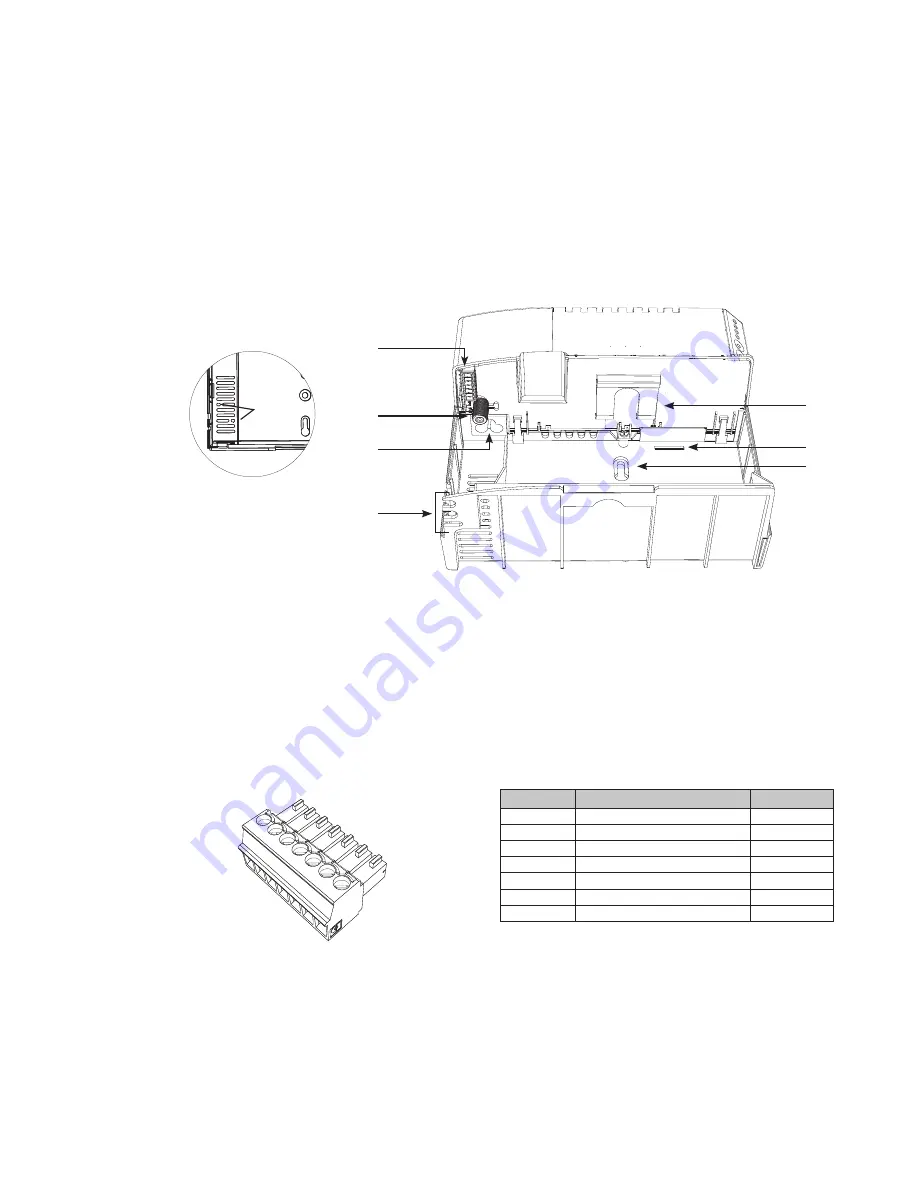
Pin
Connection
Wire gauge
1
Positive (+)
16AWG
2
Negative (-)
16AWG
3
Signal Return
24AWG
4
AC FAILURE
24AWG
5
REPLACE BATTERY
24AWG
6
BATTERY MISSING
24AWG
7
BATTERY LOW
24AWG
7
6
5
4
3
2
1
1
8
7
6
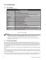
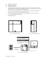
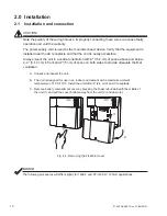
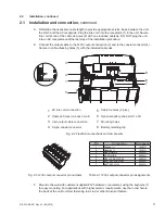
D. Determine the necessary cable length to provide appropriate service loops between the unit,
the ONT, and the AC receptacle. Plug the line cord into the receptacle (1) in the unit. Secure
line cord at one of the cable tie holes (2) with one included cable tie.
DO NOT plug the unit
into an AC receptacle until the last step of the installation procedure.
E. Connect the output cable to the 12Vdc output connection (3) and to the coaxial connector (4).
Secure in cable dressing holes (5) with the
included cable ties.
1
2
4
3
3
4
2
Cable tie holes (2 plcs.)
Optional battery strap slot (1 of 2)
Mounting holes
Battery retaining clip
5
6
7
AC line cord connection
Cable tie holes
(on back of unit)
7-pin output cable connection
F-type coaxial connector
Fig. 2-2 FlexPoint connections and components
5
8
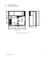
F.
Mount to the wall with customer-supplied #12 hardware or equivalent, using the keyholes (7)
for easy mounting. For applications with higher seismic requirements, use the round hole in
the back of the unit for direct fastening to a stud or other structural feature.
Fig. 2-3 12Vdc output connector pin numbers
Table 2-1 12Vdc output connector pin assignments
Summary of Contents for FP1208-F-5A
Page 19: ......


