Alpha CD12S Installation And Servicing Instructions Download Page 36

36

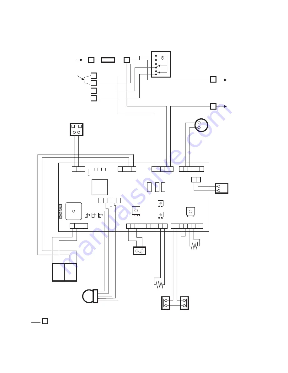
9.2  FUNCTIONAL FLOW WIRING DIAGRAM

Alpha CD12S/20S/28S - Wiring Diagrams

Pump

Fan

Gas Valve

Primary

Temperature

Sensor

Primary

Pressure

Switch

NO

COM

Spark

Generator

Overheat

Thermostat

Heat Exchanger

Thermal Fuse

Note:

Main Terminal Block

Flue

Temperature

Sensor

Transformer

L

N

TO CONNECT EXTERNAL CONTROL REMOVE LINK
FROM TERMINALS 1 AND 2 AND CONNECT 240 V
SWITCHED LIVE TO TERMINAL 1.

240

V

a

c

24

V

a

c

S3

S1

S2

Main

PCB

CH CAP

MAX CAP

X7

X3

1 2

X8

3

2 1

X4

1

2 3 4

X13

4

5

3

2 1

X6

4

3

2 1

X12

4

5

3 2

1

X15

4

6

5

2 3

1

X9

4

6

9

5

8

2 3

7

10

1

X11

4

6

5

8

2 3

7

1

CH SET

DHW SET

Green LED

Yellow LED

Red LED
Red LED

Fuse F1

315 mAT max

250 V

Fuse F2 and F3

2.5 AF

250 V

F1

F2

F3

1

2
3
4

5

Optional

2 Channel Clock

Fuse

F2A

1

2

3

4

230/240V ~ 50Hz
Fuse 3A

Remove link to connect
external control

N

N

L

L

N

N

Summary of Contents for CD12S

Page 1: ...Alpha CD12S G C No 41 532 16 Alpha CD20S G C No 41 532 18 Alpha CD28S G C No 41 532 20 British Gas Service Listed For use with Natural Gas only Leave these instructions with the User 0051 Nepicar Hou...

Page 2: ...gulations issued by the Scottish Development Department UK Water Regulations Byelaws Scotland Health Safety Document No 635 The Electricity At Work Regulations 1989 The installation should also be in...

Page 3: ...11 950 3 5 11 950 3 3 11 260 0 33 0 13 0 37 13 0 Room sealed chamber panel fitted Central Heating Heat Input Hs kW Gross Btu h Heat Input Hi kW Net Btu h Heat Output Hs condensing kW 50 C 30 C Btu h H...

Page 4: ...ended System Pressure cold CH Water Temp Approx max 2 5 bar 0 5 bar 82 C 3 bar 44 PSI 8 L at 0 8 bar 22 mm 22 mm 15 mm 1 0 bar 82 C 180 F 2 2 SYSTEM Burner Main Heat exchanger DHW Heat Exchanger Main...

Page 5: ...000 42 200 18 100 kW 25 40 18 70 15 60 12 35 5 30 Output 50 30 C Available pump head metres 2 3 3 5 3 8 4 0 4 6 feet 7 6 11 6 12 6 13 2 15 2 litre min 16 6 12 6 10 5 8 3 3 2 20 C 20 C Flow rate This...

Page 6: ...mostat 14 Expansion vessel 15 Automatic air vent 16 Pump 17 Drain point 18 Pressure relief valve 19 Primary pressure switch 20 Ignition electrodes 21 Flame sensing electrode 22 Venturi negative point...

Page 7: ...ally please note that the Easy Flue inner duct already has a pre determined slope towards the boiler for condensate to run back towards the boiler When additional flue extensions are used ensure the f...

Page 8: ...F 245 mm 90 bend 1 3 metre add 40 mm to F if a jig is used L B C 245 mm 2 x 45 bends 1 8 metre Fig 3 VERTICAL FLUE OPTIONS Not less than 300 mm Not less than 300 mm H Hmax 15 m Not less than 300 mm No...

Page 9: ...duced to 25 mm without effecting the performance of the boiler However to ensure the condensate plume does not affect adjacent surfaces a clearance of 300 mm is preferable 3 These clearances may be re...

Page 10: ...installation of the boiler in a room or internal space containing a bath or shower Where a room sealed boiler is installed in a room containing a bath or shower it must not be possible for a person us...

Page 11: ...le This is a device fitted in the heating return within the optional Premier Pack wall jig to remove any foreign or solid matter etc from the system Note A drain tap should be installed at the lowest...

Page 12: ...e old boiler is still working i Switch on the boiler and allow the system to heat up to the normal operating temperature ii Rapidly drain the system while the water is still hot iii Refill and chemica...

Page 13: ...the bottom of the tube Holes to face away from house Cement mortar sealing 100mm plastic tube Bottom of tube sealed Soakaway depth 400mm filled with limestone chippings 500 mm min Fig 9 External gully...

Page 14: ...Ensure line is level Rear exit hole 110 mm dia Position of 110 mm hole to be cut for side exit flue 145 mm 4 1 UNPACKING 1 The boxes required when the boiler is installed with a horizontal flue are a...

Page 15: ...ave been tightened especially the union bends Note If applicable the heating union bends supplied with the wall jig have been designed to enable the heating pipes to be routed from above and or below...

Page 16: ...ng system 3 Adjust the telescopic section of the flue to the distance L ensuring that the two labels marked TOP are aligned then seal and secure the joint between the ducts with the sealing tape suppl...

Page 17: ...er the outer duct and pull the flue assembly towards the bend locating the inner duct into the seal joint on the bend Ensure the labels marked TOP are positioned at the top before securing the flue as...

Page 18: ...rporates the seal joint Ensure the inner duct end without the seal joint is cut so that it is 20 mm longer than the outer duct Ensure that all cuts are square and free from burrs Once assembled with t...

Page 19: ...s to the terminal from outside i Remove the screws 1 in Fig 22 securing the terminal and remove the terminal by pulling it from the flue assembly Remove the screw 2 in Fig 22 securing the terminal end...

Page 20: ...minal end section from CD Easy Flue PM length C 4 x 93 bend 5 2 m C Terminal end section from CD Easy Flue Ensure there is a slope of approximately 3 back towards the Easy Flue Fig 23 Note The equival...

Page 21: ...1 for connecting to terminals 3 and 4 4 Replace the terminal block ensuring it is located correctly on the plastic pins and replace the cover 5 Ensure that there is sufficient free cable to allow the...

Page 22: ...er soundness rectifying where necessary Disconnect the filling loop from the mains supply Water may be released from the system by manually operating the drain point see Fig 2 until the system design...

Page 23: ...nd return pipes at the boiler and check the system volume and pressure Refer to Technical Data Sections 2 1 and 2 2 2 Turn off the boiler 4 Thoroughly flush out the water pipework refer to Section 3 9...

Page 24: ...er that an internal frost thermostat is fitted in the boiler and that the electrical supply to the boiler must be left on for the thermostat to operate i e the selector switch must be set to ON or FRO...

Page 25: ...will operate until the water temperature in the system reaches approximately 30 C Any other pipework outside the boiler should be protected from the risk of freezing and protected with insulation Add...

Page 26: ...lyser to the flue gas sampling point as shown in Fig 29 Notes 1 Prior to servicing it is recommended that a flue gas analyser is used to measure the performance of the boiler refer to Fig 28 for the p...

Page 27: ...rush with metallic bristles as this might damage the injector 4 Remove any deposits from the heat exchanger coils This can be done by suction or water sprayed onto the coils Ensure all electrical comp...

Page 28: ...exchanger This is to ensure the condensate trap is full of water before operating the boiler 2 Replace the combustion chamber front assembly ensuring it is correctly located 3 Ensure the electrode lea...

Page 29: ...ng is secured Secure with five screws do not overtighten 8 2 DRAINING THE BOILER Figs 2 14 Isolate the electricity supply and close the boiler gas service cock see Fig 14 Allow the boiler to cool Heat...

Page 30: ...overheat thermostat and remove it from the flow pipe 4 Fit the new overheat thermostat and re assemble in reverse order 8 10 FLUE TEMPERATURE SENSOR Fig 31 1 Gain access behind the front panel as desc...

Page 31: ...8 14 CLOCK if fitted Fig 21 Note For replacement only use an Alpha two channel clock Do not fit a single channel clock 1 Gain access behind the control panel as described in Section 8 1 2 Remove the t...

Page 32: ...ssioning Section 5 1 8 17 COMBUSTION CHAMBER INSULATION Gain access to the combustion chamber as described in Section 8 1 Front panel insulation Fig 30 1 Remove the electrodes from the combustion cham...

Page 33: ...pressure switch 3 Unscrew the switch from the primary flow pipe 4 Using the new washer supplied re assemble in reverse order When connecting the wiring to the new switch the polarity of the wires is...

Page 34: ...trap 3 Place a container under the boiler and unscrew the bowl at the bottom of the trap see Fig 14 Some water will spill from the trap 4 Remove the screw securing the trap to the bottom of the boiler...

Page 35: ...Y Gy G W Bl W Bl Pk Pk Br Bk Bl W P Fuse F2A Link Supply 230 240V 50Hz Fused at 3A 2 1 N L Pump Br Bl Gas Valve Overheat Thermostat X3 1 2 X8 3 2 1 X4 1 2 3 4 X13 4 5 3 2 1 X6 4 3 2 1 X12 4 5 3 2 1 X...

Page 36: ...TROL REMOVE LINK FROM TERMINALS 1 AND 2 AND CONNECT 240 V SWITCHED LIVE TO TERMINAL 1 240 Vac 24 Vac S3 S1 S2 Main PCB CH CAP MAX CAP X7 X3 1 2 X8 3 2 1 X4 1 2 3 4 X13 4 5 3 2 1 X6 4 3 2 1 X12 4 5 3 2...

Page 37: ...UT Pump runs and fan runs Go to section page 35 I YES Go to section page 34 D Burner output modulates until set temperature is reached Burner goes out NO YES Operation sequence successful Pump continu...

Page 38: ...y temp sensor faulty Cold resistance approx 12 14 k ohms resistance reduces with increase in temp i e when hot resistance is approximately 3 k ohms Check and correct connections wiring at sensor and P...

Page 39: ...at exchanger Do not Note J Replace primary pressure switch Replace PCB Continuity across primary pressure switch terminals Unplug leads from primary pressure switch is there 5V DC at PCB across X9 con...

Page 40: ...front Condensate trap Description British Gas GC No Alpha Pt No 1 024483 1 023999 1 023979 1 025585 1 024872 1 024388 1 024240 1 021750 1 023576 1 023673 1 024097 1 029719 1 021715 1 027959 1 024296 1...

Page 41: ...Central heating flow temperature C Central heating return temperature C FOR CONDENSING BOILERS ONLY CONFIRM THE FOLLOWING The condensate drain has been installed in accordance with the manufacturer s...

Page 42: ...4 Date Engineers name Company name Telephone No Gas Safe ID card serial No CO CO2 Initial ratio Final ratio Faults Repairs carried out Engineers signature SERVICE 5 Date Engineers name Company name Te...

Page 43: ...43 Alpha CD12S 20S 28S...

Page 44: ...been carefully prepared but we reserve the right to alter the specification at any time in the interest of product improvement Alpha Therm Limited 2011 Alpha Therm Limited NepicarHouse LondonRoad Wrot...

Reviews: