31
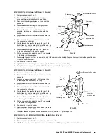
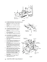
8.33 PRESSURE RELIEF VALVE OR DHW INLET MANIFOLD - Fig. 35
1.
Remove the DHW heat exchanger as described in section 8.32.
2.
Disconnect the pump unions and withdraw the pump.
3.
Disconnect the pressure relief valve outlet fitting, central heating return and mains water inlet valves.
4.
Disconnect the two small flow sensing pipes from the manifold, and the small by-pass pipe from the rear of the diverter
valve.
5.
Remove the clips (accessible from under the boiler) retaining the by-pass pipe to the manifold and diverter valve and
withdraw the pipe.
6.
Remove the screw securing the manifold to the chassis (accessible from under the boiler) and remove the manifold.
7.
Unscrew the pressure relief valve from the manifold. Fit the replacement valve using a small amount of jointing compound.
If replacing the manifold, transfer the drain point fitting to the new manifold.
8.
Re-assemble in reverse order. Ensure that all seals are in good condition and in position and that the by-pass retaining
clips are correctly fitted and locate in the slots.
9.
Refill and pressurise the system. (Refer to Commissioning, section 5.1).
Alpha 240XP and 240XE - Component Replacement
DHW heat
exchanger
DHW heat exchanger
securing screws
DHW expansion
device connection
Drain
tap
Pressure
relief valve
Fig. 34
Fig. 35
8.34 DRAIN TAP - Fig. 35
1.
Drain the boiler heating circuit as described in section 8.2.
2.
Disconnect the pump unions and withdraw the pump.
3.
Remove the drain tap fitting from the manifold and fit the replacement. Re-assemble in reverse order.
4.
Refill and pressurise the system. (Refer to Commissioning, section 5.1).
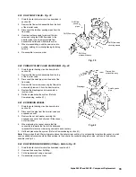
8.35 DIFFERENTIAL PRESSURE SENSOR - Refer to Fig. 36
If required, more access may be gained by removing the pump head as described in section 8.31.
1.
Drain the boiler hot water circuit as described in section 8.2.
2.
Disconnect the two small flow sensing pipes from the R/H manifold.
3.
Unscrew and remove the end fitting containing the filter/restrictor.
4.
Replace or clean components as necessary and re-assemble in reverse order.
5.
Refill and pressurise the system (if necessary). (Refer to Commissioning, section 5.1).
Summary of Contents for Alpha 240XE
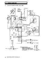
Page 35: ...35 Alpha 240XP and 240XE Wiring Diagrams 9 2 ILLUSTRATED WIRING DIAGRAM Alpha 240XE ...
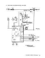
Page 36: ...36 Alpha 240XP and 240XE Wiring Diagrams 9 3 FUNCTIONAL FLOW WIRING DIAGRAM Alpha 240XP ...
Page 37: ...37 Alpha 240XP and 240XE Wiring Diagrams 9 4 FUNCTIONAL FLOW WIRING DIAGRAM Alpha 240XE ...

