background image

27

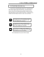
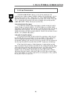
5.2 RS-232 Menu Selection Icons

Icons have been placed throughout this section to easily guide you to

key commands using remote terminal emulation.  The icons provide short
cuts to desired display screens without having to step through various
menus.  To use the icons, simply enter the number contained in the icon
screen while you are in the terminal emulation mode.  A dark screen icon
with white numbers accesses one of the 7 main menus.  A light screen icon
with black numbers directly accesses the chosen sub-menu function.

5. RS-232 TERMINAL COMMUNICATION

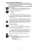
PC Communication Icons (used in this manual)

5

55

The dark screen icon with white lettering accesses
one of the main menus.  In this example, the #5
(USER PARAMETERS) will appear.

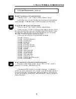
The light screen icon with black lettering directly
accesses a sub-menu. In this example, the  #55
(SET TEST FREQUENCY) will appear.

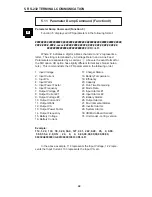
This function is not independently selectable as a
sub-menu item.  It is included as part of the USER
PARAMETERS main screen selection.

Summary of Contents for CFR 1000

Page 1: ...F R O M A L P H A T E C H N O L O G I E S Operator s Manual Alpha CFR 600 CFR 600XT and CFR 1000 U N I N T E R R U P T I B L E P O W E R S U P P L I E S ALPHA TECHNOLOGIES ...

Page 2: ...Alpha CFR 600 CFR 600XT and CFR 1000 Operator s Manual U N I N T E R R U P T I B L E P O W E R S U P P L I E S 1995 Alpha Technologies 017 100 B0 001 7 95 ...

Page 3: ... SYMBOLS APPEAR SERVICING SHOULD BE PER FORMED ONLY BY QUALIFIED PERSONNEL DANGEROUS VOLTAGE A DANGEROUS VOLTAGE EXISTS IN THIS AREA USE EXTREME CAUTION ATTENTION IMPORTANT OPERATING INSTRUCTIONS FOLLOW THESE INSTRUCTIONS CLOSELY WARNING TO REDUCE THE RISK OF FIRE AND SHOCK HAZARDS DO NOT EXPOSE THIS UNIT TO RAIN OR MOISTURE SAVE THESE INSTRUCTIONS THIS MANUAL CONTAINS IMPORTANT INSTALLATION AND O...

Page 4: ... THE UPS REAR PANEL DO NOT EXCEED THE OUTPUT RATING OF THE UPS USE PROPER LIFTING TECHNIQUES WHENEVER HANDLING THE UPS OR AN EXTERNAL BATTERY PACK THE UPS CONTAINS MORE THAN ONE LIVE CIRCUIT EVEN THOUGH AC IS NOT PRESENT AT THE INPUT IT MAY BE PRESENT AT THE OUTPUT ALWAYS SWITCH THE UPS BATTERY CIRCUIT BREAKER TO OFF BEFORE CONNECTING OR DISCONNECTING AN EXTERNAL BATTERY PACK THIS GREATLY REDUCES ...

Page 5: ...rnal Modem 2 5 Communication Interface Options 10 RS 232 Monitoring Control Applications Rear Panel Connectors RS 232 Connector Standard CFR UPS Desktop I2 D LAN Interface Connector External I2 D Connector External Alarms Connector EPO Emergency Power OFF Switch 3 INSTALLATION 16 3 1 Pre Installation 16 Site Preparation Utility Circuit Breaker Grounding Standby Generators 3 2 Connecting the CFR 17...

Page 6: ...Reference 28 5 4 Menu Commands Overview 29 5 5 System Parameters 31 5 6 Input Parameters 32 5 7 Output Parameters 33 5 8 Battery Parameters 34 5 9 User Parameters 35 5 10 Maintenance Parameters 40 5 11 Parameter DUMP Command 42 5 12 Event Descriptions 43 5 13 RS 232 Terminal Setup 47 6 MAINTENANCE 48 6 1 CFR Maintenance 48 6 2 Battery Maintenance 48 6 3 Battery Testing 49 6 4 Removing the CFR Fron...

Page 7: ...R provides you with a wide range of power management options using your choice of interface devices The Standard Interface Device displays vital UPS operating parameters including Alarms and allows you to manually self test the UPS The Intelligent Interface Device provides you with precise Voltage Current and Frequency information plus maintains an on going record of all Alarm and Line Failure Eve...

Page 8: ...ery backup the Alpha CFR UPS constantly maintains 1 output regulation without using precious battery power Even with input voltage fluctuations as great as 10 or 25 the output remains constant regardless of load ISOLATION Electromagnetic and Radio Frequency Interference EMI and RFI can damage semiconductors and have devastating effects on critical data The CFR UPS input is totally isolated from th...

Page 9: ...rovides vital load information to eliminate guess work associated with matching the appropriate load to your unit The Alpha CFR displays the existing load and whenever the load exceeds the rated output an Overload indicator is illuminated GENERATOR READY The CFR UPS is equipped with a frequency sense circuit along with a constant slew frequency synchronization circuit to provide trouble free opera...

Page 10: ... AC Line Cord 2 Operator s Manual 3 Any other ordered options SAVE THE ORIGINAL SHIPPING CONTAINER In the event the UPS needs to be returned for service it should be packaged in its original shipping container If the original container is not available make sure that the unit is packed with at least three inches of shock absorbing material to prevent shipping damage Note Do not use popcorn type ma...

Page 11: ...s and receptacle plates to facilitate your most demanding communication and powering needs 2 2 The CFR Front Panel The CFR front panel comes equipped with a Standard Interface Device SID or an optional Intelligent Interface Device I2 D to display vital UPS operating parameters The front panel can be easily removed for service or battery access by loosening the two screws located in the lower grill...

Page 12: ...The standard RS 232 serial interface allows for connection to a host computer dumb terminal for remote monitoring control and calibration of the UPS Use a straight through serial cable to connect the UPS to the computer LAN Interface Connector DE 9 Female Connector The LAN Interface connector provides dry contact status monitoring and output shutdown capability on a DE 9 female connector Used by b...

Page 13: ...plate Label EXTERNAL BATTERY Connector AC Input Line Cord External Ground Lug BATTERY Circuit Breaker Warning Labels 2 3 CFR Rear Panel Exhaust Fan The UPS contains a rear panel exhaust fan to ensure maximum cooling protection during all modes of operation OUTPUT Receptacle Plate The load equipment to be protected connects to the rear panel output receptacles Styles vary depending upon country fre...

Page 14: ...vice provides you with vital UPS operating parameters from front panel LED s see section 4 2 The Standard Interface also has a load indicator to help you determine precise loading on your UPS plus Manual Start and Alarm Off switches To ensure optimum backup performance the Standard Interface comes with a self test feature which lights the Service LED whenever a problem is detected ...

Page 15: ...oing record of UPS alarms and power anomalies by time date and type of occurrence Whenever a UPS alarm condition occurs such as Line Failure Low Battery Warning Low Battery Shutdown or Service it is displayed by the front panel indicators and recorded in the History Log External Modem optional The optional modem that comes with the desktop I2 D provides access to the unit via a phone line Service ...

Page 16: ...t device connected to your LAN network Alpha Technologies provides the AlphaNet C family of UPS monitoring software and SNMP agents to manage your network requirements You can use the AlphaNet C shutdown software to monitor the CFR in a network environment and to perform an orderly system shutdown when the battery becomes low during extended line fail situations AlphaNet C shutdown software inform...

Page 17: ...rms Connector External I2 D Connector LAN Interface Connector Pin 1 Pin 1 RJ 45 External Alarms MMJ External I2 D Figure 5 CFR UPS Connector Identification and Pin out Rear Panel Connectors Below are the various communication connectors as they appear on the back of the CFR UPS The photographs show the pin numbering for the different connector types ...

Page 18: ...ngs with SID Baud Rate 1200 Parity None Stop Bits One Data Bits 8 Handshaking XON XOFF Communication Settings with I2 D Baud Rate 300 to 9600 Parity None Even or Odd Stop Bits 1 or 2 Data Bits 7 or 8 Handshaking RTS CTS RS 232 cable to computer or terminal Use standard straight through type Internal CFR connections 1 2 3 4 5 6 7 8 9 1 2 3 4 5 6 7 8 9 1 2 3 4 5 6 7 8 9 1 2 3 4 5 6 7 8 9 RS 232 Conn...

Page 19: ...using the RS 232 ASCII terminal commands see section 5 RS 232 Terminal Communication This port has the following pin out 2 5 Communication Interface Options continued 13 Pin out DE 9 connector Female Using basic UPS monitoring software you can monitor and shutdown the CFR through this port In network applications your UPS monitoring software can perform an orderly shutdown on the network Basic UPS...

Page 20: ...RGENCY POWER OFF contacts A switch contact can be hard wired to the UPS to completely shut down the system in the event of an emergency such as a fire In an emergency the switch must be depressed shorted for at least 1 5 seconds The UPS will shut down approximately 2 seconds after the signal is recognized The switch connected to pins 7 and 8 must be electrically isolated up to 1500VAC isolation is...

Page 21: ...cts 6 LOW BATTERY N C contacts 7 8 Low Battery Warning Line Failure Line Present N C Battery OK N O Emergency UPS Shutdown Switch Wall Mounted NOTE Cable length must not exceed 100 feet Use twisted or shielded wire N C Normally Closed N O Normally Open External Alarms Connector Pin out with EPO Switch Option EPO Emergency Power OFF Option Pin out RJ 45 connector centered key Pin 1 External Alarms ...

Page 22: ...of grounding requirement To ensure optimum performance from your UPS always install a hardwired ground A qualified electrician should also inspect the existing wiring in the building prior to installation to verify proper grounding Standby Generators The CFR is equipped with a frequency sense circuit along with a constant slew frequency synchronization circuit to optimize operation with most stand...

Page 23: ...ipment connected to the UPS at the single point ground lug located on the CFR s rear panel Note Consult your local electrical code to ensure prescribed grounding practices THE UPS UTILIZES A TRANSFORMER TO PROVIDE EXCELLENT ISOLA TION AND VOLTAGE REGULATION DURING NORMAL OPERATION THE UPS WILL BE WARM TO THE TOUCH BUT NOT HOT ENOUGH TO BURN THE TRANSFORMERS HAVE BEEN COATED WITH A LACQUER FINISH W...

Page 24: ... 3 Slide the cover plate to the left and insert the battery pack s connector into the UPS Secure the connector to the UPS using the Phillips screw 1 4 Switch the EBP and CFR BATTERY breakers ON and test the unit for proper operation 18 3 INSTALLATION Note Battery Pack can be installed along side or underneath the CFR UPS Figure 7 CFR 600 and EBP External Battery Pack 3 3 External Battery Pack BATT...

Page 25: ... the increased load up to 100 If the OVERLOAD LED lights decrease the load by switching equipment OFF one unit at a time until the OVERLOAD LED goes OFF WARNING DO NOT RUN THE UPS IN AN OVERLOADED CONDITION Manual Self test Press and hold for several seconds the MANUAL START switch located on the Standard Interface Panel when the UPS is running on AC line power LINE PRESENT LED ON The unit will te...

Page 26: ...t connected to the UPS OFF 2 Switch the rear panel BATTERY circuit breaker OFF This will prevent the UPS from initiating LINE FAILURE operation when AC power is removed 3 Unplug the CFR s AC power cord from the wall receptacle BATTERY Circuit Breaker AC LINE Power Cord Figure 8 UPS Shutdown ...

Page 27: ... When used in conjunction with the CFR s rear panel Form C contact closures UPS status information can be sent directly to a Local Area Network see section 2 5 SERVICE LED LINE PRESENT LED TEST LED LINE FAILURE LED LOW BATTERY SHUTDOWN LED LOW BATTERY WARNING LED ManualStart HoldtoTest Switch Alarm OFF Switch OUTPUT LOAD LEDs Figure 9 Standard Interface Device 4 OPERATION 21 ...

Page 28: ...he percentage of the load Output Shutdown Pending The TEST LED will flash to indicate that a UPS output shutdown is pending to occur When the operator gives an output shutdown command either via the RS 232 serial port or by the LAN Interface port the UPS delays the shutdown for a programmable period before actually switching off the output Output Shutdown In Progress The five OUTPUT LOAD LEDs will...

Page 29: ...peration The green LINE PRESENT LED indicates that the UPS is running on AC line utility mains power Line Failure AC Input Out of Tolerance Whenever AC line voltage becomes unacceptably high or low 10 25 or the line frequency exceeds 3 the LINE PRESENT LED flashes and the LINE FAILURE LED lights indicating the UPS is running on backup power NOTE High generator THD can also cause this condition Lin...

Page 30: ...r discharge damage to the batteries In critical applications an additional power source such as a generator should be used until utility line power returns Test The yellow TEST LED indicates that the UPS is simulating a LINE FAILURE to self test the backup capabilities of the unit If during the one minute test the UPS fails to supply backup power it resumes LINE PRESENT operation without interrupt...

Page 31: ...RESENT LED OFF The switch can also be used to test the UPS backup capabilities LINE PRESENT LED ON without interruption to the load Output Load Display The green 25 50 75 and 100 LED s indicate the loading on the UPS Whenever the output load exceeds the rated output of the UPS the red OVERLOAD LED lights Note Each successive LED lights depending upon the load If the UPS has a 75 load displayed the...

Page 32: ... or by typing the number associated with the desired functions See section 5 3 RS 232 menus have a hierarchical format The top level menu which is also called the OPENING MENU can be accessed by pressing the ENTER key which sends a carriage return character This menu lists the numbers for accessing other sub menus plus displays the current LINE status and pending ALARM conditions The figure below ...

Page 33: ...hite numbers accesses one of the 7 main menus A light screen icon with black numbers directly accesses the chosen sub menu function 5 RS 232 TERMINAL COMMUNICATION PC Communication Icons used in this manual 5 55 The dark screen icon with white lettering accesses one of the main menus In this example the 5 USER PARAMETERS will appear The light screen icon with black lettering directly accesses a su...

Page 34: ... 55 SET TEST FREQUENCY 56 TRANSMIT UNSOLICITED ALARMS 58 SET USER SECURITY CODE 59 SET MAINTENANCE SECURITY CODE CFR SOFTWARE VER MICRO BOARD SER NO EEPROM VERSION NO POWER BOARD SER NO 501 START SHUTDOWN WHEN DELAY IS SET 502 START OUTPUT SHUTDOWN 503 CANCEL OUTPUT SHUTDOWN 504 RECOVER OUTPUT SHUTDOWN ONLY WHEN AC LINE RESTORED 505 SET OUTPUT SHUTDOWN DELAY 506 SET OUTPUT SHUTDOWN DURATION 507 SH...

Page 35: ...ssage is sent to indicate the result You may also schedule a self test using commands 53 to 55 Shutting OFF the Inverter to Save Battery Commands 507 and 508 can be used when the UPS is in the inverter mode to switch the inverter OFF to prevent a deep battery discharge during extended line failures The UPS CFR switches to normal operation when input line is restored Note This command will drop the...

Page 36: ...u to customize the CFR detection and warning levels There should be no need to change these setting unless wider or narrower detection tolerances are required Transmitting Unsolicited Alarms The UPS can automatically transmit alarm messages in ASCII format to notify a status change or a power problem as it occurs You can enable or disable this option by using commands 510 and 509 respectively 5 RS...

Page 37: ...y Temperature Displayed in degrees C Ambient Temperature is measured inside the UPS in the vicinity of the battery compartment Start Test Self Test can be initiated by selecting this menu The test duration default is 60 seconds Stop Test Self Test can be terminated prior to the full duration of the test run time 1 11 12 5 RS 232 TERMINAL COMMUNICATION 31 ...

Page 38: ...1 Amps Volt Amps The apparent input power of the UPS calculated by multiplying input voltage by the input current i e 663 VA Power in Watts The true input power of the UPS calculated in Watts i e 600 Watts Power Factor The ratio of true power power actually consumed to apparent power simple product of voltage and current at the input of the UPS i e 0 89 Line Frequency The frequency of the AC Line ...

Page 39: ...t and should read 0 Current Not available on this unit and should read 0 Volt Amps The apparent output power of the UPS calculated by multiplying output voltage by the output current i e 663 VA Power in Watts The true output power of the UPS calculated in Watts i e 600 Watts Power Factor The ratio of true power power actually consumed to apparent power simple product of voltage and current at the ...

Page 40: ... until the batteries are recharged Note If external batteries are connected their voltage will be reflected as well Battery Current When the UPS is running in LINE PRESENT mode the average DC charger current is displayed i e 2 1 Amps When the UPS is running in INVERTER mode the battery charge current is zero 0 Charger Status When the UPS is in LINE PRESENT mode the charger keeps the batteries char...

Page 41: ...nu items 56 and 509 511 for a detailed description Automatic Output Shutdown The output of the CFR can be turned off by sending a command via the RS 232 port using a computer or terminal Refer to menu items 501 508 a for detailed description menu items 501 506 are intended for scheduled shutdown even when the AC line is present 507 and 508 items can be used to switch the inverter ON and OFF to pre...

Page 42: ...presents 6 hours NOTE In the absence of an I 2 D the CFR does not have a real time clock on board and therefore the timing function may drift slightly over a period The self test takes 1 minute to complete Set Test Frequency XXX xxx off or dd days dd represents days The user can activate the auto self test feature by setting the test frequency to every dd days The self test will start at the value...

Page 43: ...he factory default setting is 1111 Start Shutdown When Delay is Set xxx xxx Yes or No Default value is No This command sets the Output Shutdown Start Mode If this option is set to No the CFR waits for a shutdown command menu item 502 to start the shutdown sequence However if this option is set to Yes the CFR starts a shutdown sequence when the output shutdown delay is set menu item 505 Changing th...

Page 44: ...en delay is set menu item 501 is set to Yes then it also acts as a shutdown command and the count down for shutting down the unit starts immediately there is no need to issue a 502 command This feature requires the USER SECURITY CODE for activation Set Output Shutdown Duration HH MM SS hh mm ss This command sets the Output Shutdown Duration which is the guaranteed down time after an output shutdow...

Page 45: ...nput out of tolerance UPS002 input blackout UPS003 inverter on UPS004 line mode UPS005 low battery warning UPS006 low battery shutdown UPS007 overload UPS008 load OK UPS009 temperature high UPS010 temperature OK UPS011 service required UPS012 UPS malfunction UPS013 self test Inv on UPS014 self test passed line mode UPS015 self test failed Delay Transmission of Inverter On Unsolicited Alarms Invert...

Page 46: ...creasing this value will make the UPS more sensitive to a slow high amplitude line disturbance surge Slow Detect Lo Ref Increasing this value will make the UPS more sensitive to a slow low amplitude line disturbance brownout by raising the brownout detection level Note The Slow Detect Hys Lo Ref should also be adjusted by the same amount Slow Detect Hi Ref Increasing this value will make the UPS m...

Page 47: ...ne fault has been corrected It will also increase the time required to resume LINE PRESENT operation Battery Warning Ref Increasing this value will increase the time before a LOW BATTERY WARNING occurs thus allowing the batteries to drain more of their charge before a warning is given Decreasing this value will allow more run time between LOW BATTERY WARNING and SHUTDOWN 79 78 5 RS 232 TERMINAL CO...

Page 48: ...Temperature 3 Input VA 19 Efficiency 4 Input Watts 20 Capacity 5 Input Power Factor 21 Run Time Remaining 6 Input Frequency 22 Mode Data 7 Output Voltage 1 23 Input Alarms 1 8 Output Current 1 24 Input Alarms 2 9 Output Voltage 2 25 Battery Alarms 10 Output Current 2 26 Output Alarms 11 Output Watts 27 Environmental Alarms 12 Output VA 28 Inverter Alarms 13 Output Power Factor 29 System Alarms 14 ...

Page 49: ...arning level detected BAT_VOLT_HI battery over voltage level detected FAIL_SELF_TEST failed self test BATT_FLT battery fault has been detected OUTPUT VOLT_LO output voltage low has been detected VOLT_HI output voltage high has been detected PWR_OVLD output power overload has been detected VA_OVLD output VA overload has been detected OVER_V_FLT output over voltage fault has been detected SHORT_CCT ...

Page 50: ...n output power while in the self test mode Check the batteries and circuit breakers Note This condition activates the SERVICE alarm along with an audible alarm which can be cleared by pressing the ALARM OFF or MUTE key Battery Fault BATT_FLT The battery charger is not able to supply the proper amount of current or voltage to the batteries This condition usually indicates that the batteries are not...

Page 51: ...t of the UPS is too heavily loaded If this is not corrected the unit may go into a shutdown condition to protect the UPS s internal circuitry Output VA Overload VA_OVLD The output VA overload alarm is triggered when the RMS current exceeds the rating of the UPS Reduce the load on the output of the UPS to prevent overheating Output Over Voltage Fault OVER_V_FLT The output overvoltage fault alarm in...

Page 52: ... LINE due to instability of the frequency If the UPS is operating from a generator check the frequency and adjust it if necessary Serv Code 2 Micro software reset The internal watch dog circuit has detected a fault and reset the software Contact Alpha to help determine the cause of the fault Serv Code 3 Micro hardware reset A micro hardware reset is activated as part of the power on condition If t...

Page 53: ... GND 8 9 24 25 1 2 TxD 3 RxD 4 5 GND 6 7 CTS 8 RTS 9 1 2 RxD 3 TxD 4 5 GND 6 7 RTS 8 CTS 9 To IBM PC Serial Port To CFR RS 232 Port DE 9 Male To CFR RS 232 Port To IBM PC Serial Port DE 9 Male to DE 9 Female DE 9 Male to DE 25 Female RS 232 Cable Diagrams The RS 232 port on the CFR follows the Data Communication Equipment DCE pinout To connect this port to a terminal or a host computer which uses ...

Page 54: ...ariables including operating temperatures number of discharges over the life of the battery charging characteristics and low voltage cell cutoff The Alpha CFR complies with all factory recommendations for charging and discharging batteries to ensure optimum performance and the longest possible battery life During normal operation the UPS batteries will tend to increase in capacity over the first t...

Page 55: ... the test plug the AC Line cord back into the wall receptacle 3 To determine the reserve time available allow the UPS to continue until it reaches LOW BATTERY SHUTDOWN Warning This will cause the load to go down Make a note of the time Subtract the LOW BATTERY WARNING time to determine your available reserve time 4 Switch the load OFF Plug the AC Line cord back into the wall receptacle The LOW BAT...

Page 56: ... UPS from the AC wall receptacle 4 If an external battery pack is connected to the UPS remove the connector from the UPS rear panel 5 Loosen the two 2 Phillips screws from the UPS front panel located in the lower grill Carefully pull the lower part of the front panel away from the UPS and lift the panel straight up 6 Remove the eight 8 Phillips screws from the sides of the UPS 7 Carefully lift the...

Page 57: ...ire from the battery s quick connect tab 5 Remove the battery fuse assembly from the center two battery quick connect tabs see Fig 17 6 Slip the two front ends of the plastic battery straps towards the buckles Fig 19 7 Loosen straps and remove foam cushion in front of the batteries 8 Carefully remove both batteries through the left side of the CFR chassis WARNING Do not let the battery terminals c...

Page 58: ...fasten terminal 5 Loosen the screws on the battery terminals on the left side and remove the battery fuse assembly CFR 600XT or wire assembly CFR 1000 6 Slip the two front ends of the plastic battery straps towards the buckles Fig 19 7 Loosen straps and remove foam cushion in front of the batteries 8 Carefully remove both batteries through the left side of the CFR chassis WARNING Do not let the ba...

Page 59: ...6 MAINTENANCE 6 5 Internal Battery Replacement continued 53 Figure 19 Battery Tie down Strap Loop side view ...

Page 60: ...put circuit breaker OFF and BATTERY circuit breaker OFF AC line voltage too high or low or UPS is in its synchronization mode BATTERY breaker tripped or Internal charger fuse open or Loose or corroded battery cables or Bad batteries Overloaded output or Shorted output No Output Power LINE PRESENT OFF LINE FAILURE OFF Unit does not resume LINE PRESENT operation when power returns LINE PRESENT ON or...

Page 61: ...and or use an electrical circuit other than that used by the UPS ITEMS TO BE PERFORMED ONLY BY A QUALIFIED TECHNICIAN SYMPTOM CAUSE REMEDY No output voltage during utility outage LINE PRESENT OFF LINE FAILURE OFF LOW BATTERY SHUTDOWN ON Batteries do not charge LOW BATTERY SHUTDOWN ON Battery voltage below low voltage cutout after long outage or Battery voltage below low voltage cutout after severa...

Page 62: ...5 VDC Failure 50 ON PWR BRD EPROM Failure 25 Flashing Self Test Failure 25 ON Battery Over Voltage Charger Fault The OUTPUT LOAD LED s located on the front panel of the Standard Interface Device are designed to display UPS fault conditions once the unit has detected an internal problem indicated by the SERVICE LED This information provided by the LED s is extremely useful during troubleshooting an...

Page 63: ... SERVICE LED ON ALARM OFF Switch pressed and held Call Alpha Wait for line power to return Check wiring Reduce ambient temperature Alarm will reset when temp returns to safe level Contact Alpha Contact Alpha Contact Alpha Contact Alpha Check batteries and retest unit Contact Alpha if unit continues to fail Contact Alpha Fast Detector Low Sensitivity Fault PLL Fault Instability in line freq from ge...

Page 64: ...Note Do not use popcorn type packing material Returns should be prepaid and insured COD and freight collect can not be accepted ALPHA TECHNOLOGIES DOES NOT ASSUME RESPONSIBILITY FOR DAMAGE CAUSED BY THE IMPROPER PACKAGING OF RETURNED UNITS 6 9 Parts and Ordering Instructions To order parts contact the Alpha Technologies Customer Service Department directly at United States 360 647 2360 Canada 604 ...

Page 65: ...mm x 248mm x 610mm EBP 24E 8 5 W x 21 5 H x 31 D 216mm x 546mm x 787mm Weights 60 Hz Units 50 Hz Units CFR 600 52 lbs 39 5 kg 56 lbs 26 kg CFR 600XT 69 5 lbs 24 kg 74 lbs 33 6 kg CFR 1000 93 5 lbs 42 4 kg 94 lbs 42 5 kg EBP 24A 35 lbs 16 kg 35 lbs 16 kg EBP 24C 125 lbs 57 kg 125 lbs 57 kg EBP 24E 314 lbs 142 kg 314 lbs 142 kg The EBP 24A is an external 24 volt battery pack pre wired with two 17 Ah...

Page 66: ...regulated maintenance free Battery Voltage 24 VDC Batt Low Volt Cutout 19 5 VDC 25 load 21 VDC 25 load Charger Linear 3 5 A max Charger Voltage 27 6 VDC at 250 C adjustable Operating Temp 320 1040 F 00 400 C Heat Output 260 BTU 404 BTU Indicators Line Present Line Failure Low Battery Shutdown Low Battery Warning LED audible alarm Test Service and Output Load Controls Manual Start Test Alarm OFF Co...

Page 67: ...dling or repair fee will be necessary prior to returning the unit THIS 24 MONTH WARRANTY IS IN LIEU OF ALL OTHER WARRANTIES EXPRESSED OR IMPLIED INCLUDING BUT NOT LIMITED TO IMPLIED WARRANTIES OF MERCHANTABILITY AND FITNESS FOR A PARTICULAR PURPOSE IN NO CASE SHALL ALPHA TECHNOLOGIES BE LIABLE FOR ANY CONSEQUENTIAL DAMAGES FOR BREACH OF THIS OR ANY OTHER WARRANTY EXPRESSED OR IMPLIED WHATSOEVER AN...

Page 68: ...62 ...

Page 69: ... CIRCUIT BREAKER S OFF TO DE ENERGIZE THE CIRCUIT EMERGENCY SHUTDOWN PROCEDURE 1 Switch the rear panel BATTERY circuit breaker OFF 2 Unplug the AC power cord from the wall receptacle or the back of the unit If hardwired switch the main panel AC breaker to the UPS OFF NOTE Press the wall mounted EPO switch to switch OFF the Battery Circuit Breaker only on CFR 1000 units equipped with this option EM...

Page 70: ...126 Schwabach Tel 49 9122 997303 FAX 49 9122 997321 MIDDLE EAST Alphatec P O Box 6468 3307 Limassol Cyprus Tel 357 5 375675 FAX 357 5 359595 CANADA Alpha Technologies 5700 Sidley Street Burnaby B C V5J 5E5 Tel 604 430 1476 FAX 604 430 8908 UNITED STATES Alpha Technologies 3767 Alpha Way Bellingham WA 98226 Tel 360 647 2360 FAX 360 671 4936 017 100 B0 001 7 95 ALPHA TECHNOLOGIES ...

Reviews: