background image


___________________________________________________________________ 

Alpha ESS Co., Ltd. 

Page 26 of 46


Your Smart Energy 

Installation 

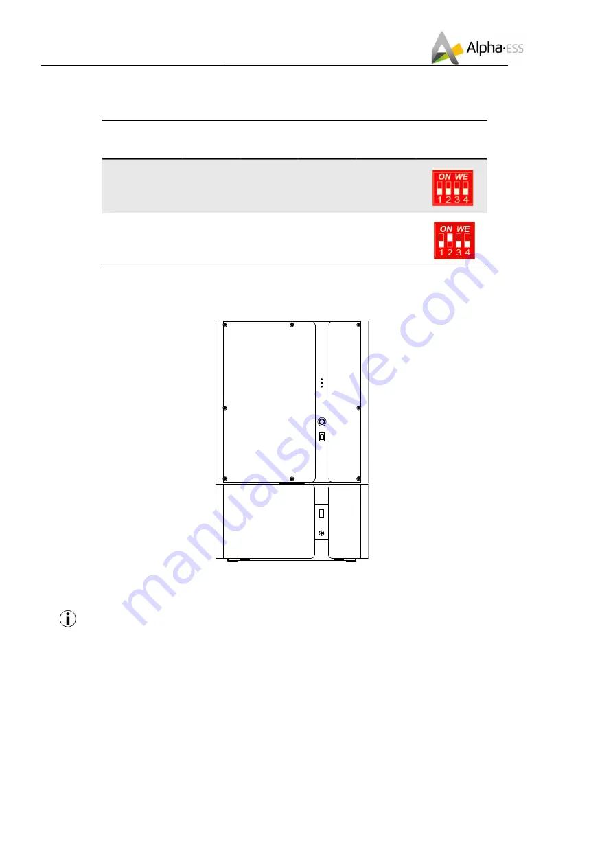
If there are more than two batteries to be connected, please refer to DIP switch configuration table as 
below: 

Battery 
Position.


DIP 1


DIP 2


DIP 3


DIP 4


DIP Switch


Non-bottom 
battery


(incl. B3-bat)


OFF 

OFF 

OFF 

OFF 


Bottom 
battery


OFF 

ON 

OFF 

OFF 


Bottom battery is the battery farthest from the inverter. 

Step 15: Switch on the 63A DC breaker of SMILE-B3 and M4856-P, Fix the maintenance cover of the 
battery and recover the front panel.  


Step 16: Please connect the wiring harness on the back of the upper cover plate of B3 and switch on 
the 80A DC breaker. Then re-cover the B3 upper cover plate, use the M5 internal hexagonal wrench to 
tightly lock the upper cover screw and insert the 8 white plugs. 

Note:  the  upper wiring harness  from  EMS  shall  be  connected  to the  back  upper part,  the 

below wiring harness from BMS shall be connected to the back below part. Please pay attention 
to the positive and negative pole of the button switch wires. 

The suggested torque for B3 upper cover plate is 2.6 N.m±10%. 


Summary of Contents for Storion-SMILE-B3

Page 1: ...V07 Installation Operation Manual Energy Storage System ESS Storion SMILE B3 ...

Page 2: ......

Page 3: ...d Tel 86 0 513 806 868 91 E mail info alpha ess com Website www alpha ess com Add Jiu Hua Road 888 High Tech Industrial Development Zone Nantong City 226300 Jiangsu Province Australia Alpha ESS Australia Pty Ltd Tel 61 1300 968 933 E mail australia alpha ess com Website www alpha ess com au Add Suite 1 Level 1 530 Botany Road Alexandria NSW Italy Alpha ESS Italy S r l Tel 39 0 599 239 50 E mail in...

Page 4: ...tem before reading the manual Version Information Version Date Contents V01 Nov 30th 2018 Newly compiled manual V02 Dec 5th 2018 Modified the connection diagram of meters Added the notice of external connection of backup and grid neutral line in Australia V03 Jan 9th 2019 Modified side screen print and internal component layout V04 May 5th 2019 Added instruction of installation location for AU Add...

Page 5: ...stem Installation 13 2 4 1 Installation Site and Environment 13 2 4 2 Installation Tools 14 2 4 3 SMILE B3 Installation 15 2 4 4 Battery Expansion 20 2 4 1 Electricity Meter Wiring 27 3 Operation 34 3 1 Switch on 34 3 2 Switch off 34 3 3 Emergency Procedure 34 3 3 1 Emergency Handling Plan 34 3 3 2 Hazards 35 3 3 3 Fire 35 4 WiFi Module Configuration 36 5 System Registration 39 5 1 System Setup in...

Page 6: ......

Page 7: ...ustomer s setting Under the auto mode SMILE B3 will store surplus renewable energy onto the battery and discharge battery to supply power to local loads when renewable energy is not enough SMILE B3 is equipped with 3 buttons friendly human machine interaction system More importantly SMILE B3 is stable safe and reliable The normal schematic is as shown in Figure 1 1 Figure 1 1 Storion SMILE B3 Syst...

Page 8: ...ature or humidity exceeding the permitted range Please do not use wet hands to touch the system Do not place heavy objects on the top of the system Do not damage the system using sharp objects Do not install or operate the system in the inflammable and explosive environment or high humidity environment Do not install explosive gas and the battery pack in the area that containing highly flammable s...

Page 9: ...gy Introduction Risk of injury by hoisting or falling system Inverters and batteries are heavy and can cause personal injury if the inverter or battery is improperly lifted or dropped during transport or when attached or removed from walls Lifting and transporting Storion SMILE B3 is conducted by more than 1 person ...

Page 10: ...customers including Table 1 Parts List of B3 Storion SMILE B3 8 x M8 60 8 x M6 gasket 1 x installing support 8 x white plug 2 x CT 100A 3000 1 1x installation manual 4 x M4 12 screws 1 x WiFi module optional Table 2 Parts List of Battery Expansion Accessory Package Storion SMILE B3 Battery Expansion Accessories Optional 6 x Screw M5 10 1 x Positive Power Line 2 x Negative Power Line 1 x Battery Co...

Page 11: ...SMILE B3 External View Table 3 SMILE B3 System LED Display LED Status Description normal Normally on Normal system operation Single flicker system standby or self inspection Extinguishing out of order fault Extinguishing fault free Normally on out of order com Normally on Normal network connection Flicker connecting to the server Extinguishing un connected network 1 2 3 ...

Page 12: ...ge 10 of 46 Your Smart Energy Installation Table 4 SMILE B3 Battery LED Display LED Outer Ring Light Flicker Status SOC Status Description Standby green light flicker 1s work green light flicker 10s SOC 5 5 SOC 25 25 SOC 50 50 SOC 75 75 SOC 95 SOC 95 Figure 2 2 Storion SMILE B3 Front View ...

Page 13: ... Definition Name Description BMS Additional battery BMS communicate cable connect DRMs DRED connect port only for AU CT1 PV CT communicate cable CT2 Grid CT communication cable BAT Additional battery power positive cable connect BAT Additional battery power negative cable connect BACKUP Critical load connect GRID Grid connect Figure 2 4 Storion SMILE B3 Rear View 80A battery switch ...

Page 14: ...nstallation fail to meet the standards and other relevant requirements Fail to observe local safety regulations Transportation damage including paint scratches caused by friction in packaging during transportation Once the container package is unloaded and the damage is confirmed claims shall be put forward directly to the transport or insurance company Fail to comply with any all user manuals ins...

Page 15: ...gh space to open Sufficient room for maintenance Figure 2 5 Limit the Distance to an Adjacent Object 2 4 1 Installation Site and Environment The following sites are not allowed installation a wall cavities b on roofs not specifically deemed suitable c areas of access egress d under stairways e under access walkways f sites where the freezing point is reached like garages carports or other places g...

Page 16: ...stralia or New Zealand you must follow these rules If the installing place is not Australia or New Zealand and there are no these rules you must not follow these rules 2 4 2 Installation Tools The following tools are required to install the equipment Wire Cutter Cable clamp Screw Driver Set M5 Hexagon screwdriver or wrench Percussion Drilling NOTE Use properly insulated tools to prevent accidental...

Page 17: ...ging Step 1 Take out Storion SMILE B3 from the packaging box as shown in Figure 2 6 Figure 2 7 Stand Positioning Step 2 first use the percussion drill M10 drill to drill holes in the wall with depth 65mm then install and place the stand 1 Insert the expansion pipe into the drilled hole Then pass the tapping screw through the spacer and tighten it with the cross screwdriver as shown in Figure 2 7 ...

Page 18: ... shown in Figure 2 8 Figure 2 9 Take Down Storion SMILE B3 Upper Cover Plate Step 4 Use the M5 internal hexagon wrench to unscrew the screws After pulling out the connecting wire harness on the back of the upper cover plate remove the B3 upper cover plate to prepare wiring as shown in Figure 2 9 Note the internal 63A and the external 80A switch must be switched off to prevent short circuit In any ...

Page 19: ...ng position for Storion SMILE B3 is as shown in Figure 2 10 please use the M4 12 screw Figure 2 11 Backup and Grid Wire Harness Wiring Step 6 Connect Backup and Grid wire harness to 6 pin terminal strip as shown in Figure 2 11 Note in Australia the neutral of backup and grid circuit should be externally connected on the neutral bar The suggested torque for the waterproof contact is 3 75 N m 10 ...

Page 20: ...Wire Harness Wiring Step 7 Complete for installing CT as shown in Figure 2 12 Note CT communication wires can be connected directly through the silica gel ring of the M20 waterproof contact no need to make the on site network line The maximum outer diameter of the network cable does not exceed 14mm Figure 2 13 Ethernet Communication Cable Wiring ...

Page 21: ...wn in Figure 2 14 If you will install extrenal M4856 P for expansion please goto section 2 4 4 directly Step 9 before re covering the upper cover plate please turn on the internal 63A switch Figure 2 15 Re cover the Upper Cover Plate Step 10 the wiring is completed please connect the wiring harness on the back of the upper cover plate Then re cover the B3 upper cover plate use the M5 internal hexa...

Page 22: ... Expansion If you don t install external M4856 P battery for expansion please ignore this section Figure 2 16 Installing stand holders Step 1 Switch off the 63A DC breaker Open the accessory package and install the two stand holders Figure 2 17 Installing position limiter Step 2 Install the position limiter on the bottom as shown in Figure 2 17 ...

Page 23: ... the front panel as shown in Figure 2 18 NOTE The box must be placed in the direction of the label and only remove the packaging in upwards direction Removing the packaging in other directions is wrong Step 4 Unscrew the four screws on the bottom of M4856 P Place the battery holder near the position limiter Step5 Drill in the holes of the battery holder Insert the expansion pipe into the drilled h...

Page 24: ...t Energy Installation Step 6 Remove the position limiter NOTE If the position limiter is not limited SMILE B3 can be not removed alone Step 7 Install the two battery brackets as the above directions Step 8 Place the battery into the battery holder and fix it with four screws which have been unscrewed in Step 4 ...

Page 25: ...ion Step 9 Please drill holes directly on the wall at the marking positions of the brackets Insert the expansion tube and pass the expansion screw through the gasket and lock with a screwdriver NOTE If the drill is not long enough you can mark the hole positions before drilling Step 10 Remove the maintenance cover before wiring ...

Page 26: ...mart Energy Installation Step 11 Pass the red positive power cable through the two BAT waterproof rings And fix it on the copper bars inside the battery and inverter Step 12 pass the black negative power cable through the two BAT waterproof rings And fix it on the copper bars inside the battery and inverter ...

Page 27: ... communication cable through the COM waterproof ring of BAT and BMS waterproof ring of INV And insert it into the corresponding port anyone of the two RJ45 port Step 14 If there is only one M4856 P to be connected switch off the DIP2 in SMILE B3 and switch on the DIP2 in M4856 P 63A DC Breaker DIP Switch of B3 DIP Switch of M4856 P 63A DC Breaker ...

Page 28: ...eaker of SMILE B3 and M4856 P Fix the maintenance cover of the battery and recover the front panel Step 16 Please connect the wiring harness on the back of the upper cover plate of B3 and switch on the 80A DC breaker Then re cover the B3 upper cover plate use the M5 internal hexagonal wrench to tightly lock the upper cover screw and insert the 8 white plugs Note the upper wiring harness from EMS s...

Page 29: ...ADL 3000 or ACR10R CT 100A 1 3000 ADL 3000 Three phase electricity meter with or without CT ACR10R Three phase CT electricity meter with CT Table 6 CT meter ratio and accuracy table Model CT ratio Accuracy ADL3000 N CT 300A 5A CT 60 0 6 kWh ADL3000 N CT 400A 5A CT 80 0 8 kWh ADL3000 N CT 400A 1A CT 400 4 0 kWh ACR10R 100A CT 100 1 0 kWh ACR10R 120A CT 120 1 2 kWh 2 4 5 1 CT The CTs connection is a...

Page 30: ...____ Alpha ESS Co Ltd Page 28 of 46 Your Smart Energy Installation 2 4 5 2 Electricity Meter ADL 3000 if optional ADL 3000 connection without CT without Meterplug Figure 2 20 ADL 3000 connection without CT without meterplug Note terminal 7 8 connecting RJ 45 PIN 3 6 ...

Page 31: ... Alpha ESS Co Ltd Page 29 of 46 Your Smart Energy Installation ADL 3000 connection without CT with Meterplug Figure 2 21 ADL 3000 connection without CT with meterplug ADL 3000 connection with CT without Meterplug Figure 2 22 ADL 3000 Connection with CT without meterplug ...

Page 32: ...of 46 Your Smart Energy Installation ADL 3000 Connection with CT and Meterplug Figure 2 23 ADL 3000 Connection with CT and meterplug Note In AC system the both two meters addresses should be set please refer to 2 4 5 5 1 2 4 5 3 Electricity meter ACR10R if optional Figure 2 24 ACR10R Connection ...

Page 33: ...ion is released in SMILE B3 EMS firmware version V1 00 33 or above In AC system and the mixed installation of CT and meter situation the meter address should be also set in the meter please refer to 2 4 5 5 1 ADL3000 and 2 4 5 5 2 ACR10R 2 4 5 5 Meter setting 2 4 5 5 1 ADL3000 Step 1 The initial interface of the meter normal working interface is as shown below Step 2 Click the SET button to enter ...

Page 34: ...SET button to enter the following interface Step 9 Click the SET button again to enter the save interface Step 10 Click the Enter button to enter the following interface press the up and down arrow keys and set no to YES to save the configuration Step 11 Click the Enter button and the setting ends 2 4 5 5 2 ACR10R Step 1 This is the initial interface of the meter click the Set button Step 2 Click ...

Page 35: ...e setting interface Step 4 In the setting interface select Comm option enter the communication setting interface Step 5 Set the communication address and communication baud rate in the communication setting interface When the meter is used as the Grid meter DC AC Hybrid system the address is set to 005 When it is used as the PV meter AC Hybrid system the address is set to 006 The baud rate is set ...

Page 36: ... until the battery LED lights Step 4 Turn on the 80A battery switch of B3 system Step 5 If backup load is applied turn on the external backup AC breaker if not then keep it off 3 2 Switch off Step 1 If backup load is applied turn off the external backup AC breaker Step 2 Turn off the 80A battery switch of B3 system Step 3 Press the button on the battery until the battery LED off Step 4 Turn off th...

Page 37: ...area thoroughly with soap and water and seek medical attention Ingestion Induce vomiting and seek medical attention 3 3 3 Fire If a fire breaks out in the place where the battery pack is installed perform the following countermeasures Fire extinguishing media Respirator is not required during normal operations Use Novel 1230 FM 200 or dioxide extinguisher for battery fire Use an ABC fire extinguis...

Page 38: ... the APP by scanning the QR code Figure 4 1 and directly connect to Storion SMILE B3 by WiFi module Figure 4 1 AlphaESS APP Step 1 Open Alpha ESS APP click the Wi Fi configuration button and enter the WiFi configuration interface as shown in Figure 4 2 Figure 4 2 Network Setting Step 2 After that please check whether your mobile phone has connected to the system hotpot as shown in Figure 4 3 Figur...

Page 39: ...ease open the Wi Fi network list Please find the hotpot named after the product SN in WLAN list and connect to it If the Wi Fi module is Yilian as shown in Figure 4 7 please enter the password 12345678 otherwise please connect directly After successful setting please go back to APP and click Next Figure 4 4 Open WiFi network list Figure 4 5 WLAN Password Figure 4 6 ZLG WiFi module Figure 4 7 Yilia...

Page 40: ...successful click next as shown in Figure 4 8 and Figure 4 9 Figure 4 8 WiFi Setting Figure 4 9 Configuration Success Step 5 set the basic parameters and you can see the details of equipment click submit button as shown in Figure 4 10 and Figure 4 11 Figure 4 10 Basic Parameter Setting Figure 4 11 Equipment Details Note If without registration please register account according to the hint after dow...

Page 41: ...haven t yet registered need to click Register to visit the registration page Please refer to AlphaCloud Online Monitoring Webserver Installers User Manual which you can get from AlphaESS sales and get license number from relevant sales from Alpha ESS Log in to your installer account and choose Storage System Maintenance Install new system to register new system at Alpha ESS ...

Page 42: ...SMILE B3 must be carried in the installer monitoring To do this follow the steps below Step 1 Please login in the installer account click the list of storage systems and enter the SN 5 1 1 Basic Information Step 2 After selecting the correct system enter System Setup interface Enter in the Basic Information and input below information Address Zip code Contact name E Mail address Currencies and Tel...

Page 43: ... individually After that you must specify whether you have installed a CT or an electricity meter ADL3000 or ACR10R and in the case of electricity meters please further select with or without CT were connected 1 If a CT is installed select directly the point CT 2 If a meter is installed select the item meter a If a CT meter is installed select in addition to the second point CT and set the CT rati...

Page 44: ... 42 of 46 Your Smart Energy System Registration 5 1 4 Other Information Step 5 Finally select the Other Information submenu and set the following parameter ACDC mode it should be AC mode Time zone Data upload frequency SMILE B3 has second level data you can choose it as 10s data if you wish ...

Page 45: ...the normal monitoring In addition a part of our warranty is based on this connection to our webserver The data produced prior to registration can be synchronized to the webserver Please use the following steps Step 1 Open the portal www alphaess com Step 2 Please fill in Username Password and click Login if you have already registered If not please register by filling in the following web form Fig...

Page 46: ...tar are compulsory and you can select the finally users or installation procedures Serial number EMS serial number please see the nameplate of the inverter Username 5 15 letters numbers Note User name cannot be changed anymore after creation Password 5 15 letters numbers characters More detailed information is available in the online monitoring Web server User manual which can be downloaded from A...

Reviews: