XRM2-CLINK-MINI-RX User Manual
V1.0 - 08/03/2018
Table Of Contents
1
Introduction ...................................................................................................................................... 1
2
Installation ........................................................................................................................................ 1
2.1
Handling instructions ..................................................................................................................... 1
3
Specification .................................................................................................................................... 2
3.1
Connectors .................................................................................................................................... 2
3.2
Mating Cableform .......................................................................................................................... 2
3.3
Miscellaneous ................................................................................................................................ 2
4
Order Code ....................................................................................................................................... 2
5
Related Documents ......................................................................................................................... 2
6
Design Examples ............................................................................................................................. 2
7
Pinout ................................................................................................................................................ 2
7.1
Camera Link Pinout ....................................................................................................................... 2
7.2
Control Pinout ................................................................................................................................ 9
7.3
Debug Pinout ................................................................................................................................. 9
7.4
RS232 thru-hole header (JP2) ....................................................................................................... 9
8
Board Layout .................................................................................................................................. 11
List of Tables
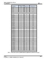
Table 1
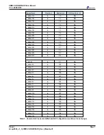
Camera Link Connector 1 (Base/Medium/Full Configuration) ........................................................... 2
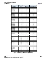
Table 2
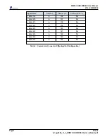
Camera Link Connector 2 (Base Configuration) ................................................................................ 4
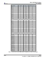
Table 3
Camera Link Connector 2 (Medium/Full Configuration) .................................................................... 6
Table 4
Base/Medium/Full Select Control ...................................................................................................... 9
Table 5
RS232 Interface ................................................................................................................................. 9
Table 6
LED Indicators ................................................................................................................................... 9
Table 7
Aux Connectors ................................................................................................................................. 9
Table 8
RX input ........................................................................................................................................... 10
Table 9
TX output ......................................................................................................................................... 10
List of Figures
Figure 1
XRM2-CLINK-MINI-RX Block Diagram .............................................................................................. 1
Figure 2
XRM2-CLINK-MINI-RX Board Layout (front) ................................................................................... 11
Figure 3
XRM2-CLINK-MINI-RX Board Layout (back) ................................................................................... 11


