ADM-PA101 User Manual
3.9 Configuration
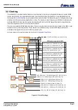
There are three main ways of configuring the ACAP on the ADM-PA101:
•
From QSPI Flash memory, at power-on, as described in
•
From uSD Flash memory, at power-on, as described in
•
Using USB cable connected at either USB port
3.9.1 Configuration From QSPI Flash Memory
The ACAP can be automatically configured at power-on from two 1 Gbit QSPI flash memory devices configured
as an x8 dual parallel SPI device (2x Micron part number MT25QU01GCBB8E12).
The ADM-PA101 is shipped with a simple PCIe endpoint bitstream which should be visible to the operating
system (using Windows Device Manager or “lspci” in Linux) in order to provide confidence that the card is
working correctly when installed in a system. On request, Alpha Data can pre-load custom bitstreams during
production test. Please contact [email protected] in order to discuss this possibility.
At power-on, the ACAP attempts to configure itself automatically according to the mode pins as described in
. If the mode is set to QSPI24 or QSPI32, the ACAP will search on the header of the binary that has
been flashed into the card. This normally results in SPIx8 configuration.
The Alpha Data System Monitor is also capable of reconfiguring the flash memory and reprograming the ACAP.
This provides a useful failsafe mechanism to re-program the ACAP even if it drops off the PCIe bus. The system
monitor can be accessed with avr2util over USB at the front panel and rear edge.
3.9.1.1 Building and Programming QSPI Configuration Images
You can start with one of the example Vivado projects(.xpr format) that are available for customers in the early
access section of the PA101. You can request access to them by messaging [email protected]
Every early access project contain the implementation results of the example design in question, so you can use
Hardware Manager to program the FPGA binary directly. Below are described the steps to do a QSPI Flash
programming. You would need to set up the equipment first:
•
Connect the PA101 to a PCIe slot of a host PC
•
Make sure SW1-1, SW1-2, SW1-3, SW1-4 are all ON in the PA101 (see
)
•
Connect an USB cable between a test PC and the PA101's micro-USB connector
•
Turn on the host PC with the PA101 connected to it
Now, it is time run the actual flash programming commmands through Vivado's GUI:
•
Open Vivado -> Open Project(select .xpr file) -> Select HW Manager -> Open Target -> Auto Connect
•
Right click on xcvc1902_1 -> Add Configuration Memory Device -> search for
'cfgmem-qspi-x8-dual_parallel', selecting it -> click OK
•
A message asking the user to configure the device now will pop up. Click OK accepting it
•
Now, copy the path to the PDI image in the 'Initialization PDI' field, and click OK. This will program the
QSPI Flash with the example design that you have opened. If you have a .BIN file instead, use the path for
that binary file and leave the other fields as are
If you followed the previous steps, the FPGA should have been correctly configured. In order to test that, turn the
host PC with the PA101 OFF, change the switches SW1-1, SW1-3, SW1-4 ON and SW1-2 OFF. Then turn the
host PC back ON. You should see both DONE_L and STAT_0 LEDs ON after a few seconds(see
)
3.9.2 Configuration From uSD Flash Memory
The ACAP can be automatically configured at power-on from the Micro Secure Digital card (uSD) slot along the
Page 19
Functional Description
ad-ug-1430_v1_2.pdf


