background image

11

Alpha SY9-24 - Installation

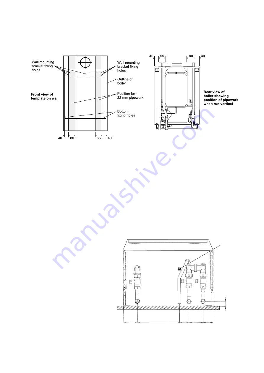
Fig. 10

4.4

FIT THE BOILER - Refer to Fig. 10

1.

Lift the boiler and locate it on the mounting bracket.

2.

Fit the bottom screws to secure the boiler in position.

Fig. 11

- Heating flow (22 mm)

- Heating return (22 mm)

- Gas inlet (22 mm)

- Pressure relief valve (15 mm)

- Heating drain point

70

212.5

47.5

70

50

A

B

C

D

E

23

4.5

CONNECT THE PIPEWORK - Fig. 11

1.

Thoroughly flush out all the water pipework.

2.

The valves/fittings have been factory fitted, however, check that all the connections underneath the boiler have been
tightened, especially the union bends.
To gain access to all the connections remove the bottom tray by removing the four fixing screws. When all the connections
have been checked for soundness replace the tray and secure with the four screws previously removed.
The heating union bends have been designed to enable the heating pipes to be routed from above and/or below using the
same fitting.
Note: When soldering to the boiler union bends, ensure the bends are not connected to the valves, otherwise the internal
seals may be damaged.

3.

Connect the system pipework to the boiler.
Note: Do not forget that the pressure relief valve discharge pipe must be routed clear of the boiler to a drain in such a
manner that it may be seen, but cannot cause injury to persons or property.

4.

Ensure that all the valves are closed (spindle flats at right angles to valve) and do not turn on the water or gas supplies at this stage.

Summary of Contents for SY9-24

Page 1: ...om Sealed Gas Fired System Boiler Alpha SY9 24 G C No 41 532 01 Service Listed For use with Natural Gas only Leave these instructions with the User Nepicar House London Road Wrotham Heath Sevenoaks Kent TN15 7RS For Technical help or for Service call ALPHA HELPLINE Tel 0870 3001 964 ...

Page 2: ...allation and Use Regulations All current Building Regulations issued by the Department of the Environment i e Approved Document L1 Building Standards Scotland Consolidation Regulations issued by the Scottish Development Department Health Safety Document No 635 The Electricity At Work Regulations 1989 The installation should also be in accordance with the following British Standard Codes of Practic...

Page 3: ...ting Heat Input kW Gross Btu h Heat Output modulating kW Btu h Burner Pressure mbar Settings in wg Gas Rate m h ft h Burner Main Heat exchanger Main Burner Injectors Flue Outer Duct Flue Inner Duct Stainless steel Copper 1 30 mm x12 White Aluminium 2 3 COMPONENTS Central Heating Sealed System Max Working System Pressure Min System Pressure Max System temperature Pressure Relief Valve Setting Expan...

Page 4: ... 1 m for vertical terminal assembly Maximum flue length 4 m Each additional 90 Bend is equivalent to 1 m of flue length Each 45 Bend is equivalent to 0 5 m of flue length The Vertical Flue terminal assembly is equivalent to 1 m of flue length 2 8 AVAILABLE PUMP HEAD FOR CENTRAL HEATING gal min 3 7 2 8 2 3 1 8 1 5 Btu h 79 500 60 000 50 000 40 000 31 700 kW 23 3 17 58 14 65 11 63 9 3 metres 2 4 3 8...

Page 5: ... sealed chamber 6 Fan 7 Air pressure switch 8 Flue hood 9 Overheat thermostat 10 Expansion vessel 11 Automatic air vent Fig 2 12 Pump 13 Drain point 14 Pressure relief valve 15 Ignition electrodes 16 Flame sensing electrode 17 Flue sampling point 18 Gas service cock 19 Primary pressure switch 20 On off valve 2 off 21 Automatic by pass ...

Page 6: ...rvicing must always be maintained Note A cupboard or compartment used to enclose the boiler must be designed and constructed specifically for the purpose i e comply with the Building Regulations 3 4 FLUE SYSTEM Fig 3 The flue system must be installed in accordance with BS 5440 1 For horizontal flues ensure there is a slight downward slope towards the terminal Flue components are available as follo...

Page 7: ...TAL FLUE OPTIONS Lmax 4 metres L B C E 185 mm Alpha SY9 24 General Boiler Information L B C 185 mm C B E C B E B F B C L B E F 185 mm 90 bend 1 metre L B C 185 mm 2 x 45 bends 1 metre Fig 3 VERTICAL FLUE OPTIONS ...

Page 8: ...le have access the terminal must be protected by a terminal guard A suitable guard is available from Tower Flue Components Ltd Vale Rise Tonbridge Kent TN9 1TB 3 6 BOILER LOCATION The boiler is not suitable for external installation The boiler must be installed on a flat vertical wall which is capable of supporting the weight of the boiler The boiler can be fitted to or adjacent to a wall comprisi...

Page 9: ...formation 3 8 FILLING THE CENTRAL HEATING SYSTEM Figs 6 7 The system design pressure cold should be set to 1 0 bar This pressure is equivalent to a static head see Fig 5 of 10 2 metres of water Provision should be made to replace water lost from the system This can be by manual or automatic means as shown in Figs 6 and 7 The position for connecting an automatic make up vessel is indicated in Fig 5...

Page 10: ...tray 4 2 CLEARANCES REQUIRED Fig 8 Fig 8 4 3 PREPARE THE WALL Figs 9 10 1 Decide upon the position of the boiler taking into account the clearances required for servicing and the flue terminal position 2 Tape the template to the wall ensure it is level and the right way up and mark the position of the holes for the boiler mounting bracket and bottom fixings If rear exit flue is used mark the posit...

Page 11: ...e bottom tray by removing the four fixing screws When all the connections have been checked for soundness replace the tray and secure with the four screws previously removed The heating union bends have been designed to enable the heating pipes to be routed from above and or below using the same fitting Note When soldering to the boiler union bends ensure the bends are not connected to the valves ...

Page 12: ...he outer duct of the flue immediately before the terminal Push the flue assembly through the 127 mm flue hole so that the collar completely passes through the wall Then pull the flue assembly back into the correct position Visually check that the collar is sealing the outside wall and that it is not restricting any of the openings of the flue terminal 10 Position the seal and clamp two screws supp...

Page 13: ... length finished wall thickness 172 mm Side flue Outer air duct length finished wall thickness the distance from the inside wall to the side of the boiler 145 mm Inner flue duct length finished wall thickness the distance from the inside wall to the side of the boiler 182 mm 5 When measuring the outer duct measure from the end of the tube as shown in Figs 12 and 13 6 Cut both the inner and outer d...

Page 14: ...e is pulled out of its clamp the live and neutral wires become taut before the earth wire The main terminal block can be removed by pulling it off the pins to give easy access to the terminals Do not switch on the electrical supply at this stage 3 If an external control i e room thermostat or external clock is to be fitted remove the terminal block cover and remove the link between terminals 1 and...

Page 15: ...er may be released from the system by manually operating the drain point see Fig 2 until the system design pressure is obtained The system design pressure cold should be between 0 75 and 1 25 bar Refer to sections 3 7 and 3 8 System volume and Filling the system 5 2 BOILER CONTROLS Fig 15 Alpha SY9 24 Commissioning 5 COMMISSIONING Fig 15 5 3 TEST FOR GAS SOUNDNESS AND PURGE THE SUPPLY 1 With the b...

Page 16: ...er s requirements 3 If the boiler is not to be handed over immediately close the boiler gas service cock and switch off the electrical supply 4 If there is any possibility of the boiler being left during frost conditions then the boiler and system should be drained refer to section 8 2 It is recommended that a label is attached to the boiler drawing attention to the fact that the system has been d...

Page 17: ...operating 6 2 FROST THERMOSTAT The boiler incorporates a built in frost thermostat which automatically turns on the boiler and pump if the water in the boiler falls below 8 C providing the electrical supply is on and the selector switch set to The boiler will operate until the water temperature in the system reaches approximately 40 C 6 3 PUMP If the electrical supply is on and the boiler has not ...

Page 18: ...llowing water to escape from the system check that this is actually happening 6 Refill vent and re pressurise the system as necessary Refer to Commissioning section 5 1 If the system pressure exceeds 2 5 bar when operating at maximum temperature the heating expansion vessel should be checked and re pressurised if necessary Note 1 Check the expansion vessel charge only when the system pressure is z...

Page 19: ... in position 7 Raise the control panel and secure in position with the two screws provided 8 Check the operation of the boiler Refer to Boiler Operation section 6 9 Return all controls to their original settings Alpha SY9 24 Routine Servicing Component Replacement 8 COMPONENT REPLACEMENT It is the law that any service work must be carried out by a competent person ie CORGI registered personnel War...

Page 20: ...ove the screw securing the electrode and withdraw the electrode Fit the new electrode ensuring both are positioned correctly and the spark gap is correct see Fig 18 Re assemble 1 Replace the burner ensuring it is located correctly 2 Replace the combustion chamber front cover ensuring it is correctly located especially on the sides 3 Complete re assembly as described in Routine Servicing section 7 ...

Page 21: ...n section 8 1 2 Disconnect the coil wires and pressure tube from the gas valve 3 Loosen the one screw securing the electrical plug and disconnect the plug 4 Disconnect the burner manifold union and the gas inlet pipe union from the manifold 5 Remove the two manifold screws from beneath the boiler 6 Carefully push the valve towards the rear of the boiler take care not to damage the manifold sealing...

Page 22: ...2 2 Remove the four screws securing the combustion chamber front cover and remove the cover 3 Remove the overheat thermostat section 8 9 and the CH temperature sensor section 8 17 4 Remove the right hand side baffle plate by lifting it up 5 Disconnect the two unions from the heat exchanger flow and return pipes 6 Lift up the heat exchanger off the pipes and remove it by carefully withdrawing it ou...

Page 23: ...e the system Refer to Commissioning section 5 1 8 19 PUMP Refer to Fig 23 Gain access behind the casing and drain the boiler heating circuit as described in sections 8 1 and 8 2 Pump head 1 Remove the four socket head screws securing the pump head to the body Withdraw the head remove the wiring cover and disconnect the wiring 2 Connect the wiring to the new head as follows Brown to L Blue to N Gre...

Page 24: ...bove the boiler or a rear exit flue is used it is not possible to replace the vessel in which case an additional vessel should be fitted external to the boiler in the central heating return pipe as close to the boiler as possible see Fig 5 1 Gain access behind the casing and drain the boiler heating circuit as described in sections 8 1 and 8 2 2 Disconnect the pipe from the pump inlet manifold and...

Page 25: ...25 Alpha SY9 24 Wiring Diagrams 9 1 ILLUSTRATED WIRING DIAGRAM 9 WIRING DIAGRAMS ...

Page 26: ...26 9 2 FUNCTIONAL FLOW WIRING DIAGRAM Alpha SY9 24 Wiring Diagrams ...

Page 27: ... Earth Continuity Resistance to Earth Short Circuit and Polarity with a suitable meter Note These checks must be repeated after any servicing or fault finding 3 Ensure all external controls are calling for heat and check all external and internal fuses 4 Check that the gas and water pipework has been connected to the correct connections on the boiler and all valves are open However before any serv...

Page 28: ...28 10 3 FAULT FINDING SOLUTION SECTIONS A to F Alpha SY9 24 Fault Finding ...

Page 29: ...29 Alpha SY9 24 Fault Finding 10 4 FAULT FINDING SOLUTION SECTIONS G to J ...

Page 30: ...ressure gauge Ignition electrode right Ignition electrode left Flame sensing electrode Ignition electrode lead Flame sensing electrode lead By pass assembly Combustion chamber insulation panel set Description British Gas GC No E57 720 E57 733 E57 736 E57 665 E57 666 E76 342 E57 668 E76 320 E76 374 E76 317 E76 378 E57 700 E57 702 E57 703 E57 709 E57 710 E57 712 E57 713 E57 714 E65 195 E57 717 E65 2...

Page 31: ...ETAILS OF BOILER INSTALLATION Date of Installation Name of Installer Address Postcode Telephone No Boiler Serial Number see data label on inside of left hand case panel DETAILS OF BOILER SERVICE HISTORY Date of Service Details of Service Service Engineer ...

Page 32: ...s have been carefully prepared but we reserve the right to alter the specification at any time in the interest of product improvement Alpha Therm Limited 2003 Alpha Therm Limited NepicarHouse LondonRoad WrothamHeath Sevenoaks Kent TN15 7RS Tel 0870 3001964 email info alphatherm co uk website www alpha boilers com ...

Reviews: