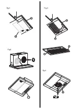
Fig.1
Ø
125150
125100
ADF 602 G - ADF 60 E
ADF 601 W
Fig.2
A
B
1
2
III II I 0
I 0
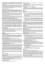
Fig.3
Fig.4
Page 1: ...ISTRUZIONI D USO OPERATING INSTRUCTIONS 552 4 852 4 389 34 598 898 81 105 280 174 20 170 BEDIENANLEITUNG ADF 602 G ADF 60 E 50 135 59 51 600 280 ADF 601 W 10401250390...
Page 2: ...Fig 1 125 150 125 150 125 100 125 100 ADF 602 G ADF 60 E ADF 601 W Fig 2 A B 1 2 III II I 0 I 0 III II I 0 I 0 Fig 3 Fig 4 A B 1 2 III II I 0 I 0 III II I 0 I 0 Fig 4 Fig 3...
Page 3: ...C D Fig 5 Fig 6 G C D Fig 5 F E G Fig 6...
Page 4: ...15 5...
Page 5: ...fondo dell apparecchio possibile applicaresuquest ultimoundistanzialediprofondit arichiesta fissandolo ai due fori situati nella parte inferiore del gruppo con le viti a corredo Collegare la riduzione...
Page 6: ...king a fixed installation acut offdevicemustbeusedtoassureomnipolardisconnection of the mains The cut off distance of the contacts must be at least 3 mm If the appliance is provided with a supply cord...
Page 7: ...b 3 B die 6 beigelegten Schrauben eindrehen Sollten die Seiten des H ngeschrankes st rker sein als 16mm schl gt die Haube an die Distanzst cke an und l t sich nicht einbauen In diesem Fall m ssen die...
Page 8: ......