


GMC1000 User Manual
Alloy Computer Products Pty Ltd Copyright ©2008
5.
Installing
the
Converter
Note:
Wear
a
grounding
device
for
electrostatic
discharge.
P2
SFP
Port
Default:
1000FDX
Insert
the
required
SFP
transceiver
and
attach
the
fibre
cable.
The
Tx,
Rx
fibre
cable
must
be
paired
at
both
ends
P1
SFP
Port
Default:
1000FDX
Optionally
Insert
the
required
SFP
transceiver
and
attach
the
fibre
cable.
The
Tx,
Rx
fibre
cable
must
be
paired
at
both
ends
P1
TP
Port
Attach
TP
Cat.
5
or
higher
cable
to
TP
port
Mode:
10/100/1000Mbps
with
NWay
6.
DIP
Switch
Settings
Converter
TP
Port
1000TP
AUTO,
FORCE
selectable:
Bit
2
of
SW1
a.
AUTO:
10/100/1000
Nway
(default)
b.
FORCE:
1000
FDX
Converter
LFP
Function
LFP
function
selectable:
Bit
1
of
SW1
a.
LFP
function:
ON
(default)
b.
LFP
function:
OFF
Fig.
3
SW1—Bit
1,
2
Configuration
and
Setting
SW1
‐
1
LFP
function:
LFP
ON
(default)
or
OFF
SW1
‐
2
TP
port
mode:
AUTO
(default)
or
FORCE
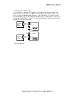
Fig.
4
Basic
Network
Configuration
LFP TP
ON AUTO
LFP TP FORCE
OFF
SW
1 2
1000Base-T
Network
1000SX/LX
Fibre
Network
RX
TX
TP/SFP-
t SFP
TX
RX
TX
RX
(P2 SFP)
(P1 SFP)
(P1 TP)


