background image


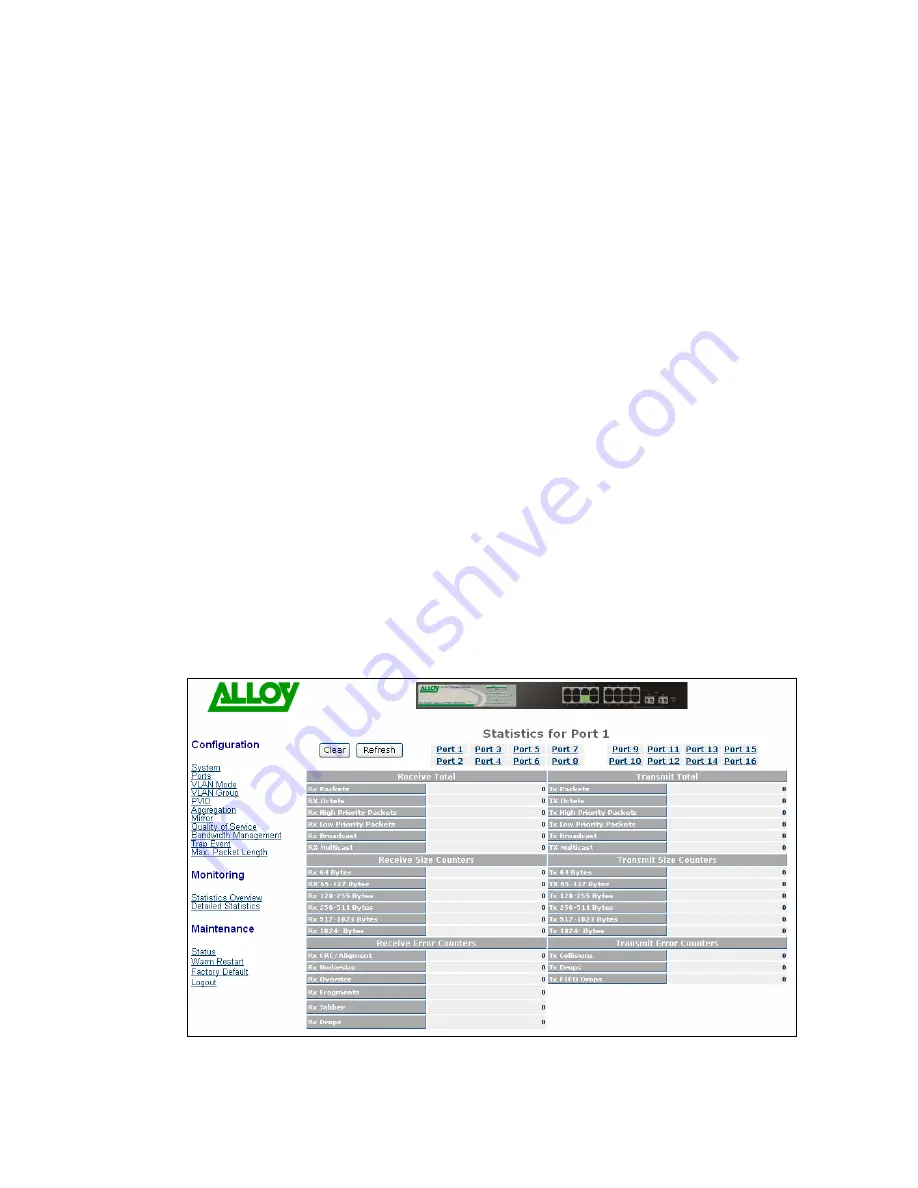
Tx 512-1023 Bytes


* Number of 512 to 1023-byte frames (includes non valid packets) 

transmitted 


Tx 1024-Bytes


* Number of 1024-maximum length byte frames (includes non valid 

packets) transmitted 


Rx CRC/Alignment


* Number of alignment errors/CRC error packets received 


Rx Undersize


* Number of short frames (64 Bytes or under) with valid CRC 


Rx Oversize


* Number of long frames (according to maximum length register) 

with a valid CRC 


Rx Fragments


* Number of short frames (64 Bytes or under) with an invalid CRC 


Rx Jabber


* Number of long frames (according to maximum length register) 

with an invalid CRC. 


Rx Drops


* Frames dropped due to the Receive Buffer being full 


Tx Collisions


Number of collisions experienced during transmission 


Tx Drops


* The number of frames dropped due to excessive collision (for 

example, due to heavy network traffic loads), late collision (for 
example, collisions caused by cable lengths in excess of 
prescribed standards), or frame aging. 


Tx FIFO Drops


* Total frames dropped due to the Transmit Buffer being full


Fig. 3.24c

38 

Summary of Contents for 16-PORT GIGABIT WEB SMART SWITCH GSS-16T2SFP

Page 1: ...Manual GSS 16T2SFP 16 Port Gigabit Web Managed Switch 16x 10 100 1000Mbps ports 2 paired SFP Ports GSS 24T2SFPV2 24 Port Gigabit Web Managed Switch 24x 10 100 1000Mbps ports 2 paired SFP Ports Version...

Page 2: ...ii June 24th 20005...

Page 3: ...LX ZX SFP Modules 10 3 OPERATION OF WEB BASED MANAGEMENT 12 3 1 WEB MANAGEMENT HOME PAGEOVERVIEW 13 3 2 SYSTEM THE SYSTEM CONFIGURATION SUBMENU 14 3 2 1 System Configuration 15 3 2 2 Port Configuratio...

Page 4: ...4 4 Logout 48 4 MAINTENANCE AND BASIC TROUBLESHOOTING 49 4 1 MAINTENANCE ENVIRONMENT 49 4 2 MAINTENANCE SWITCH COMPONENTS ATTACHMENTS 49 4 3 BASIC TROUBLESHOOTING 50 APPENDIX A TECHNICAL SPECIFICATION...

Page 5: ...for a Class A computing device pursuant to Subpart J of Part 15 of FCC Rules which are designed to provide reasonable protection against such interference when operated in a commercial environment Eu...

Page 6: ......

Page 7: ...l If the model you have purchased is the GSS 24T2SFPV2 please bear in mind that your switch has 24x 10 100 1000Mbps ports Overview of the User Manual Chapter 1 Introduction describes the features of G...

Page 8: ...1000Base LX 1310nm max range 10Km 1000Mbps singlemode 1000Base LHX 1310nm max range 40Km 1000Mbps singlemode 1000Base LHX 1550nm max range 40Km 1000Mbps singlemode 1000Base ZX 1550nm max range 70Km 1...

Page 9: ...can support up to 8 trunking groups Port trunks are useful for switch to switch cascading providing very high full duplex connection speeds Port Mirroring Port mirroring copies traffic from a specifi...

Page 10: ...policing and Broadcast Storm Control IEEE802 1Q in Q nested VLAN support Full duplex flow control IEEE802 3x and half duplex backpressure Extensive front panel diagnostic LED suite Management Easy por...

Page 11: ...es both models on the front panel of the switch The LED display area located on the left side of the panel contains a Power LED which indicates the power status of the switch and 16 24 LEDs that indic...

Page 12: ...Mbps speed is active Amber when 100Mbps speed is active Off when 10Mbps speed is active LEDS for SFP Gigabit Fibre Ports 15 16 GSS 16T2SFP or SFP Gigabit Fibre Ports 23 24 GSS 24TSFP SFP LINK ACT Gree...

Page 13: ...SLC4015 1000Mbps singlemode 1000Base LHX 1550nm max range 40Km MGBIC SLC70 1000Mbps singlemode 1000Base ZX 1550nm max range 70Km MGBIC SLC100 1000Mbps singlemode 1000Base EZX 1550nm max range 100Km MG...

Page 14: ...appable so you can plug or unplug them while the power is applied to the switch 1 Verify that the mini GBIC module is compatible with the SFP port on the switch for example some switch manufacturer s...

Page 15: ...Repeat the above steps as needed for each RJ 45 port to be connected Power On Please Note Alloy 16 24 Port Gigabit Switches use a 100 240 VAC 50 60 Hz power supply The power supply will automatically...

Page 16: ...it supports These are SX LX LHX ZX and EZX The majority of mini GBIC modules available use a LC type connector The connector types used currently on Alloy mini GBIC modules are LC and WDM SC for the f...

Page 17: ...e must be treated as Please Further in All figures denoting the range a given cable type can maximum values A number of variables can limit the actual range that can be achieved grade of cable used qu...

Page 18: ...ess 192 168 1 1 Subnet Mask 255 255 255 0 Default Gateway 192 168 1 254 Default Password admin Browse the switch via its IP address http 192 168 1 1 The following screen will be displayed and ask you...

Page 19: ...d Maximum Packet Length From this information you can ascertain the software version used MAC address port status and so on For more details please refer to Section 3 Fig 3 2 The Basic Page Layout The...

Page 20: ...onfiguration Submenu 11 functions are included in the System Configuration group Each of them will be described in detail in the following sections In diagrammatical format the functions are Fig 3 4 A...

Page 21: ...ings are made in the appropriate areas in the central grey box Function Name System Configuration Function Set IP address subnet mask default gateway system name Description password and auto logout t...

Page 22: ...are allowed in this parameter Click the apply button to update the field The default value is GSS 16T2SFP Password RW Used to set a password to access the switch s management interface Up to 16 alphan...

Page 23: ...lex The following table summarizes the functions that each media type supports Media type Nway Speed Duplex 1000M UTP ON OFF 10 100 1000M Full for all Half for 10 100 1000M Fibre ON OFF 1000M Full In...

Page 24: ...all VLAN functions This is the default setting Port based Port based VLAN simply groups ports together Ports within the same group can talk to each other Ports that are not in the same group are bloc...

Page 25: ...ed to a unique VLAN bound to Port 15 Port 15 ends up a member of 15 VLAN groups one VLAN for each port This secures intra port traffic but allows all ports access to a single uplink port 15 Each VLAN...

Page 26: ...ete VLAN groups by using the Add Group and Delete Group function buttons or click the Group ID directly to edit it Parameter ID Group ID Description When you want to edit a VLAN group you must select...

Page 27: ...Fig 3 9 Delete Group Select the check box beside the ID to delete a group Then press the Delete Group button to delete the group Fig 3 10 21...

Page 28: ...sure that you have created a Tag based VLAN with a VID of the same number For example if port 1 receives an untagged packet the switch will apply the PVID assume VID 5 to tag this packet the packet th...

Page 29: ...ed packet the switch will apply the PVID of port 1 to tag this packet and the packet will then be forwarded Tag This is an egress rule applied on data transmitted out of the port Select untag or tag T...

Page 30: ...it Ethernet ports aggregated in a logical port then this logical port has bandwidth three times as high as a single Gigabit Ethernet port 3Gbps in half duplex mode or 6Gbps in full duplex mode Fig 3 1...

Page 31: ...sed the default is Port 1 Source Port Used to set up the port that will be monitored Select the check box under the port label The valid port range is ports 1 16 3 2 8 Quality of Service QoS Configura...

Page 32: ...fault Class is High Fig 3 15 Function Name VLAN Tag Priority Function VLAN tags have 3 bits that belong to a priority flag Description These 3 bits can define 8 traffic classifications The classificat...

Page 33: ...r IP Description headers Alloy 16 24 Port Gigabit Switches can prioritise packet forwarding based on this TOS header TOS Headers include 3 bits for 8 levels of TOS Once again these 8 levels can be map...

Page 34: ...ameter Disable IP TCP UDP Port Classification Description Disables all L4 application based QoS Simple Mode Down Prioritise web browsing e mail FTP and news Enable Low prioritization for standard Inte...

Page 35: ...ect the port which your Special TCP UDP class will apply Optionally you can select to control all ports at the same time from the All selection Special UDP TCP Port Selection The following are port nu...

Page 36: ...ckets The GSS 16T2SFP switch allows mapping of these 64 classifications to High or Low priority queues Parameter IP Differentiated Services DiffServe Configuration Description Used for setting up the...

Page 37: ...f Flow Control is enabled see section 3 2 2 The limited format of the packet includes unicast broadcast and multicast The valid range is 0 1000 Broadcast Multicast for Ingress Rate Limiting Define the...

Page 38: ...t trap events and 2 configurable destination Trap Hosts Trap messages are enabled by selecting the tick box beside each event description Most events support a counter function to help identify the nu...

Page 39: ...They maximise the data to header payload ratio so that more data is sent with less header information note that both transmitting and receiving nodes need to support Jumbo Frames Fig 3 22 Parameter M...

Page 40: ...3 The Statistics Overview func counters The type of data that can be collected includes information about Frames Bytes and Errors In Fig 3 23 maximum level then it will reset and resume from 0 zero Fu...

Page 41: ...s received Total re Rx Frames The num Tx Errors The nu Rx Errors The num 3 2 Detailed Statistics Statistics unter information for a specific port 3 Function Name Detailed Function Displays detailed co...

Page 42: ...ets received Rx Multicast Number of multicast packets received Transmitted Tx Packets Number of packets transmitted TX Octets Total data transmitted in bytes Tx High Priority Packets Number of Tx pack...

Page 43: ...yte frames includes non valid packets received Rx 1024 Bytes Number of 1024 maximum length byte frames includes non valid packets received Tx 64 Bytes Number of 64 byte frames includes non valid packe...

Page 44: ...id CRC Rx Fragments Number of short frames 64 Bytes or under with an invalid CRC Rx Jabber Number of long frames according to maximum length register with an invalid CRC Rx Drops Frames dropped due to...

Page 45: ...n the switch status screen These comprise Switch status TP Port Status Fibre Port Status Aggregation VLAN Mirror Trap Event and Maximum Packet Length Status Warm Restart Maintenance Factory Default Lo...

Page 46: ...he switch Serial Number Displays the serial number assigned by the manufacturer to the switch IP Address Displays the IP address of the switch Subnet Mask Displays the subnet mask of the switch Defaul...

Page 47: ...splays the status of the link for the port Options are o 10FULL 10Mbps Full duplex o 10HALF 10Mbps Half duplex o 100FULL 100Mbps Full duplex o 100HALF 100Mbps Half duplex o 1000FULL 1000Mbps Full dupl...

Page 48: ...hernet Both supported by Alloy Gigabit Switches o Pause flow control As stipulated by IEEE standard 802 3x for full duplex operation o Backpressure For half duplex operation 3 4 1 3 Aggregation Functi...

Page 49: ...ach mode The 3 modes are o Tag Based VLAN o Port Based VLAN o Metro Mode VLAN ID Display the Group ID Description Displays the description associated with the VLAN group as defined by the network admi...

Page 50: ...scription Displays the mirror status The default is disabled Sniffer Port Displays the number of the port that is receiving the monitored data Source Port Displays the number of the port that is being...

Page 51: ...ap data warnings Link Two parameters are available for Link Traps The associated tick boxes are endorsed to activate trap data warnings The parameters are o Link Up o Link Down Link Up and Link Down c...

Page 52: ...of 1518 bytes 1532 bytes or 9216 bytes Fig 3 33 3 4 2 Warm Restart The management interface for Alloy 16 24 Port Gigabit Switches offers a Warm Restart option This simply reboots the switch with the c...

Page 53: ...tion Function Name Restore Default Configuration Function The Factory Default function will reset the current configuration Description settings of the switch and replace them with the original Factor...

Page 54: ...a manual logout function If you need to release control of the web management so that another user can access it immediately then you can manually perform a Logout with this function Management of th...

Page 55: ...taken to eliminate the ingress of particles into the switch through the ventilation points environmentally secured cabinets etc Dust will still be present in a normal office environment so considerat...

Page 56: ...ibre optic module whose transceiver is of multimode type even though the cable can be physically connected Check that the length of the cable connected to the port is within the range prescribed by th...

Page 57: ...type can have many causes However if the LED indicators on your Alloy 16 24 Gigabit switch show such problems check that network cards used in your system are functioning correctly Faulty Network Adap...

Page 58: ...802 3x Flow Control for full duplex ports Supports collision based and carrier based backpressure for half duplex ports All ports can be configured for disabled mode forced mode or auto negotiation S...

Page 59: ...he paired ports have an auto detect feature 2 SFP module slots are used to install optional mini GBIC modules primarily for fibre Gigabit Ethernet connectivity Optional SFP mini GBIC modules support L...

Page 60: ...LX WDM Singlemode Single Fibre up to 20Km Diagnostic LED System LED Power Per Port LED 10 100 1000M TP Port 1 to 16 1000M SFP Fibre Port 15 16 LINK ACT 10 100 1000Mbps SFP LINK ACT Power Requirement A...

Reviews: