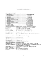


TECHNICAL SPECIFICATION
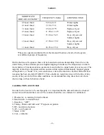
Basic Frequency Coverage
*Additional Band ............................................................ 500 KHz band width
*Crystal not supplied....................................................... 3.5 to 10 MHz
80 meter Band ................................................................. 3.5 to 4.0 MHz
49 meter Band ................................................................. 5.7 to 6.2 MHz
40 meter Band (HAM) .................................................... 7.0 to 7.5 MHz
31 meter Band (WWV@ 10 MHz).................................. 9.5 to 10.0 MHz
25 meter Band ................................................................. 11.5 to 12.0 MHz
20 meter Band (HAM) .................................................... 14.0 to 14.5 MHz
19 meter Band (WWV@15 MHz)................................... 15.0 to 15.5 MHz
16 meter Band ................................................................. 17.5 to 18.0 MHz
11 meter Band (CB) ........................................................ 27.0 to 27.5 MHz
*Crystal not supplied....................................................... 10.0 to 30.0 MHz
Number of semiconductors....4 FET, 22 TR, 13 diodes, 2 zeners and 2 thermisters
IF. Frequencies ......................2.420 MHz to 2.920 MHz (Variable) and 455 KHz
Reception ..............................AM, CW, and Single sideband (SSB)
Sensitivity - AM ....................Less than 1 microvolt for 10 db S/N ratio
Sensitivity SSB/CW ..............Less than 0.5 microvolt for 10 db S/N ratio
Selectivity..............................4 KHz at 6 db down
Visual dial accuracy ..............±200 Hz
Calibration accuracy..............Better than ±500 Hz adjacent 25 KHz calibration points after
indexing
Stability .................................Better than 500 Hz after warm-up
Image rejection......................More than 60 db
Spurious rejection..................More than 50 db
Rejection tuning ....................More than 40 db
Selection tuning.....................500 Hz at -3db
Audio output power...............Maximum 1 watt at 8-ohm load
Audio output impedance........8 ohm and 600 ohm
Headphone output .................8 ohm, panel-mounted jack accepts standard 1/4-inch plug
Antenna input impedance ......50 ohm to 75 ohm unbalanced: rear mounted type SO-239 coaxial
receptacle accepts PL-259 connector
Power source .........................120 volt AC 60 Hz and 12V DC negative ground only
Power consumption ...............10 watts
Remote stdby control.............Rear-mounted; 2 pin connector
Dimensions............................7" high, 15" wide and 10" deep
- 1 -
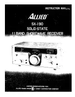
Summary of Contents for SX-190
Page 1: ......
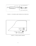
Page 7: ...FIGURE 1 3 ATTACHING CABLE TO PHONE PLUG CONNECTOR FIGURE 1 4 INSTALLATION OF GROUND 6 ...
Page 17: ... 16 ...
Page 22: ...SCHEMATIC DIAGRAM OF RF AMP 21 ...
Page 23: ...SCHEMATIC DIAGRAM OF BUFFER AMP SCHEMATIC DIAGRAM OF CALIBRATOR 22 ...
Page 24: ...SCHEMATIC DIAGRAM OF VFO SECTION 23 ...
Page 25: ...SCHEMATIC DIAGRAM OF I F AMP SECTION 24 ...
Page 26: ...SCHEMATIC DIAGRAM OF POWER SUPPLY 25 ...
Page 29: ......
Page 30: ......
Page 31: ......


