background image

Page 10  of  16

506941-01

Issue 1148

Continuous Blower

With the proper thermostat and sub-base, continuous blower 
operation is possible by closing the R to G circuit. 

Heating Sequence of Operation

The following sequence describes the operation of the gas 
heat section.

1.  A call for heat from the room thermostat starts the 

combustion air blower and the circulating air blower.

Cooling System Performance

This equipment is a self contained, factory optimized 
refrigerant system, and should require no adjustments 
when properly installed.  If however, unit performance is 
questioned, perform the following checks.

Insure unit is installed per manufacturer’s instructions and 
that line voltage and air fl ows are correct.  Refer to Table 2 
for proper superheat or subcooling values.  Check superheat 
settings by measuring presure at the suction line service 
port.  For TXV systems, measure pressure at the liquid 
service port.  Take line temperature within 2 inches of service 
port connection to its main tube.  If unit superheat/subcooling 
varies by more than table allowance, check internal seals, 
service panels and duct work for air leaks, as well as 
restrictions and blower speed settings.  If unit performance 
remains quetionable, remove charge, evacuate to 500 
Microns, and weigh in refrigerant to name plate charge.  It is 
critical that the exact charge is re-installed.  Failure to comply 
will compromise system performance.  If unit performance 
is still questionable, check for refrigerant related problems 
such as, blocked coil or circuits, malfunctioning metering 
devices or other system components.

7.  After reassembly of all parts is complete and all wires are 

reconnected, open the main manual gas shutoff valve; 
check for and correct any gas leaks.  Turn electrical 
power on, initiate a call for heat, and check for proper 
burner operation.

8.  Install burner access panel.

Heat Anticipator 
The heat anticipator setting is 0.75 amp.
 

It is important 

that the anticipator setpoint be correct. Too high of a setting 
will result in longer heat cycles and a greater temperature 
swing in the conditioned space. Reducing the value below 
the correct setpoint will give shorter “ON”  cycles and 
may result in the lowering of the temperature within the 

conditioned space.

OPERATION

Cooling System

The cooling system is a complete factory package utilizing 
an air-cooled condenser and is factory-charged with HFC-
R-410A. The compressor is hermetically sealed and base 
mounted with rubber-insulated hold-down bolts.

Cooling Sequence of Operation

When the thermostat calls for cooling, R is closed to G and 
Y (see the wiring diagram found on page 13).  This action 
completes the low voltage control circuit, energizing the 
compressor, condenser fan motor, and blower motor.

Unit compressors have internal protection. In the event there 
is an abnormal rise in the temperature of the compressor, 
the protector will open and cause the compressor to stop.

Blower Delay – Cooling

In cooling mode, the circulating air blower operation is 
delayed for fi ve (5) seconds after the compressor starts.  
The blower continues to operate for 60 seconds after the 
compressor is de-energized.  The feature is a function of 
the blower motor itself and cannot be changed.

NOTE:


There is no blower OFF delay when there is only 

a call for G (fan only).
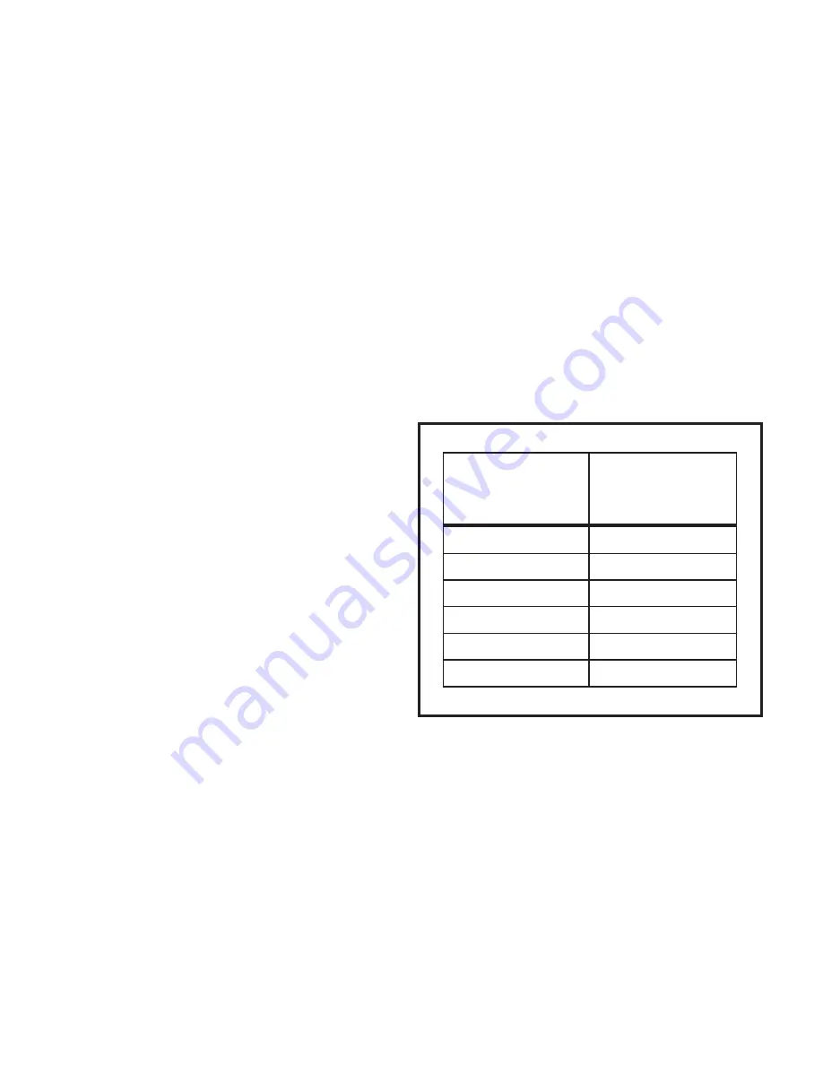
Suction Superheat

Table 2


*  This letter will vary according to furnace series.

Outdoor

Unit Model

Suction Superheat

+/- 3° @ ARI

Conditions 82° OD

80° IDDB/67° IDWB

RGE13(*)24

21°

RGE13(*)30

19°

RGE13(*)36

17°

RGE13(*)42

20°

RGE13(*)48

15°

RGE13(*)60

15°

Summary of Contents for RGE Series

Page 1: ...d home application the ductwork must be sized to achieve static pressures within the manufacturer s guidelines All other installation guidelines must also be followed Failure to do so may result in equipment damage personal injury and improper performance of the unit WARNING Never use a flame to check for gas leaks Explosion causing injury or death may occur WARNING Do not store combustible materi...

Page 2: ...a forklift while still in the factory supplied packaging The lengths of the forks of the forklift must be a minimum of 42 Inspection As soon as the unit is received it should be inspected for possible damage during transit If damage is evident the extent of the damage should be noted on the carrier s freight bill A separate request for inspection by the carrier s agent should be made in writing Lo...

Page 3: ...f a roof curb is used follow the manufacturer s Installation Instructions and be sure that all required clearances are observed see Clearances section on this page This unit is shipped with four 4 corner brackets in place on the underside of the unit see Figure 1 All four 4 brackets must be removed before unit is installed onto roof curb assembly To avoid interference with roof curb remove the out...

Page 4: ...termined that each appliance remaining connected to the common venting system properly vents when tested as outlined above return doors windows exhaust fans fireplace dampers and any other fuel burning appliance to their previous condition of use 8 If improper venting is observed during any of the above tests the common venting system must be corrected See National Fuel Gas Code ANSI Z223 1 latest...

Page 5: ... Air Conditioning Contractors of America ACCA A closed return duct system shall be used This shall not preclude use of economizers or outdoor fresh air intake It is recommended that supply and return duct connections at the unit be made with flexible joints The supply and return air duct systems should be designed for the CFM and static requirements of the job They should not be sized by matching ...

Page 6: ...parate line and installed in accordance with all safety codes listed on page 1 After the gas connections have been completed open the main shutoff valve admitting normal gas pressure to the mains Check all joints for leaks with soapy solution or other material suitable for the purpose Never use a flame to check for gas leaks Explosion causing injury or death may occur WARNING The furnace must be i...

Page 7: ...most regulator manufacturers and LPG propane gas suppliers Check all connections for leaks when piping is completed using a soapy solution Some soaps used for leak detection are corrosive to certain metals Carefully rinse piping thoroughly after completing leak detection Electrical Wiring See Figures 6 7 All wiring should be done in accordance with the National Electrical Code ANSI NFPANo 70 lates...

Page 8: ... At no time should the standby gas pressure exceed 13 w c nor the operation pressure drop below 5 w c for natural gas units or 11 w c for propane gas If gas pressure is outside these limits contact the gas supplier for corrective action 4 Adjust temperature rise to be within the range specified on the raƟng plate To Light Main Burners 1 Turn off electrical power to unit 2 Turn the thermostat to lo...

Page 9: ... d To Reassemble Reverse above steps Example The heating value of the gas is 1053 BTU cubic foot By actual measurement it takes 38 seconds for the hand on the 1 cubic foot dial to make a revolution with a 100 000 BTU HR furnace running The result is 99 750 BTU HR which is close to the 100 000 BTU HR rating of the furnace Manifold Gas Pressure Adjustment Regulator LPG Propane Gas LPG propane units ...

Page 10: ...nnected open the main manual gas shutoff valve check for and correct any gas leaks Turn electrical power on initiate a call for heat and check for proper burner operation 8 Install burner access panel Heat Anticipator The heat anticipator setting is 0 75 amp It is important that the anticipator setpoint be correct Too high of a setting will result in longer heat cycles and a greater temperature sw...

Page 11: ...pre purge period 30 seconds nominal 3 When the pre purge period has expired the ignition control energizes the main gas valve and spark electrode for a period of 10 seconds 4 If the flame sensor does not sense that a flame has been established in the 10 second interval then the ignition control will de energize the gas valve and begins a 30 second interpurge period then initiates another trial for...

Page 12: ...box Carefully remove the flue collector box without ripping the adjacent insulation 4 Using a wire brush on a flexible wand brush out the inside of each heat exchanger from the burner inlet and flue outlet ends 5 Run the wire brush down the heat exchanger tubes from the burner end 6 Brush out the inside of the flue collector box 7 Clean the combustion air blower wheel and housing Run the wire brus...

Page 13: ...506941 01 Page 13 of 16 Issue 1148 CONNECTION DIAGRAM SINGLE STAGE HEAT 230 V 3 PHASE Figure 10 ...

Page 14: ...Page 14 of 16 506941 01 Issue 1148 CONNECTION DIAGRAM SINGLE STAGE HEAT 460 V 3 PHASE Figure 11 ...

Page 15: ... All applications Ten 10 years LF24 and TUA Stainless All applications Fifteen 15 years LD24 Aluminized All applications Two 2 years LD24 Stainless All applications Five 5 years LG14 All applications Five 5 years Burners LG14 Three 3 years Compressors 4SCU13LC 4SHP13LC Five 5 years TSA TPA Five 5 years KCA KGA KHA TCA TGA THA Five 5 years RGE13 RHP13 RCE13 Five 5 years NOTE If the date of original...

Page 16: ...omponents indoor unit outdoor unit and re frigerant control devices which do not match or meet the specifica tions recommended by the manufacturer e Operation of packaged gas electric units equipped with aluminized heat exchanger with mixed air temperatures of less than 45 F 7 C f Operation of furnaces with return air temperatures of less than 60 F 16 C or operation of a furnace field installed do...

Reviews:

Related manuals for RGE Series