
507787-01
Issue 2007
Page 17 of 22
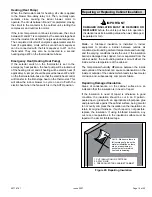
Air Handler Model
Blower Speed
.10
"
WC
.20
"
WC
.30
"
WC
.40
"
WC
.50
"
WC
-018
LOW
538
525
503
471
418
MED
688
670
639
603
548
HIGH
919
881
855
788
710
-024
LOW
677
673
657
629
592
MED
1011
979
942
803
742
HIGH
1106
1045
999
917
857
-030
LOW
871
870
853
812
769
MED
1078
1057
1024
987
936
HIGH
1311
1261
1214
1154
1086
-036
LOW
1020
972
956
909
806
MED
1276
1240
1191
1148
1086
HIGH
1559
1521
1446
1395
1327
-042
LOW
1300
1273
1250
1211
1155
MED
1527
1493
1452
1390
1345
HIGH
1816
1756
1693
1605
1528
-048
LOW
1257
1212
1157
1116
1053
MED LOW
1486
1448
1411
1364
1330
MED
1721
1675
1630
1594
1553
MED HIGH
1721
1675
1630
1594
1553
HIGH
1840
1794
1754
1721
1681
-060
LOW
1098
1049
1001
926
831
MED LOW
1624
1594
1565
1520
1492
MED
1815
1783
1758
1730
1685
MED HIGH
1903
1869
1837
1809
1764
HIGH
1981
1957
1923
1893
1861
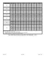
Blower Performance (CFM vs. ESP in. w.c.)
•
Cooling speeds should not be reduced below factory setting.
•
All units with electric heat approved at 0.5” maximum and medium blower speed minimum.
•
All downflow applications run on high speed when utilizing electric heat.
Table 4. BCE5C
Blower Performance (3-Speed PSC) – 240V (CFM @ ESP. – in. W. C.)


