background image

508297-01

Page 15 of 57

Issue 2219

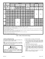
Capacity

Vent Pipe 

Dia. 

(in.)

Standard

Concentric

Flush Mount Kit

Wall Kit

Field


Fabricated

1-1/2 inch

2 inch

3 inch

51W11 (US) 

51W12 (CA)

2 inch

3 inch

71M80 (US) 

4

44W92 

(CA)

69M29 (US) 

4

44W92 

(CA)

60L46 (US) 

4

444W93 

(CA)

22G44 (US) 

4

30G28 (CA)

44J40 (US) 

4

81J20 (CA)

030 

045

1

 1-1/2

3

YES

YES

1

YES

5

 YES

2

 YES

N/A

N/A

2

3

YES

YES

1

YES

5

 YES

2

 YES

2-1/2

3

YES

YES

1

YES

5

 YES

2

 YES

3

3

YES

YES

1

YES

5

 YES

2

 YES

070

1

 1-1/2

3YES

YES

1

YES

5

 YES

2

 YES

2

3YES

YES

1

YES

5

 YES

2

 YES

2-1/2

3

YES

YES

1

YES

5

  YES

2

 YES

3

3

YES

YES

1

YES

5

 YES

2

 YES

090

2

3

YES

N/A

YES

5

 YES

N/A

YES

YES

2-1/2

3

YES

YES

5

 YES

YES

YES

3

3

YES

YES

5

 YES

YES

YES

110

2

YES

YES

5

 YES

YES

YES

2-1/2

YES

YES

5

 YES

YES

YES

3

YES

YES

5

 YES

YES

YES

135

3

YES

YES

5

 YES

YES

YES

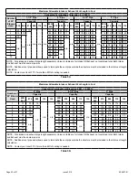
NOTE - Standard Terminations do not include any vent pipe or elbows external to the structure. Any vent pipe or elbows external to the structure must be included in total 

vent length calculations. See vent length tables.* Kits must be properly installed according to kit instructions.
1Requires field-provided outdoor 1-1/2” exhaust accelerator.
2Concentric kits 71M80 and 44W92 include 1-1/2” outdoor accelerator, when used with 045 and 070 input models. When using 1-1/2 in. piping, the pipe must transition to 

2in. pipe when used with the concentrci kit.
3 Flush mount kits 51W11 and 51W12 includes 1-1/2 in. outdoor exhaust accelerator, required when used with 045, 070 and 090 input models. When using 1-1/2 in. piping, 

the pipe must transition to 2in. pipe when used with the flush mount kit.
4 Termination kits 30G28, 44W92, 44W93 and 81J20 are certified to ULC S636 for use in Canada only.
5 See table 10 for vent accelerator requirements
6  2inch to 1-1/2 inch reducer required. must be fied required.

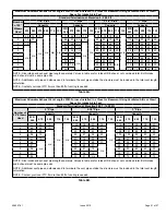
Table 3. Outdoor Termination Kits Usage

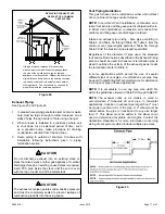
Joint Cementing Procedure

All  cementing  of  joints  should  be  done  according  to  the 

specifications outlined in ASTM D 2855.

NOTE: 

A  sheet  metal  screw  may  be  used  to  secure  the 

intake pipe to the connector, if desired. Use a drill or self 

tapping screw to make a pilot hole.

DANGER OF EXPLOSION!

Fumes from PVC glue may ignite during system check. 

Allow fumes to dissipate for at least 5 minutes before 

placing unit into operation.

 DANGER

1.  Measure and cut vent pipe to desired length.
2.  Debur and chamfer end of pipe, removing any ridges 

or rough edges. If end is not chamfered, edge of pipe 

may remove cement from fitting socket and result in a 

leaking joint.

3.  Clean and dry surfaces to be joined.
4.  Test fit joint and mark depth of fitting on outside of pipe.
5.  Uniformly apply a liberal coat of PVC primer for PVC 

or use a clean dry cloth for ABS to clean inside socket 

surface of fitting and male end of pipe to depth of fitting 

socket.

NOTE: 

Time  is  critical  at  this  stage.  Do  not  allow 

primer to dry before applying cement.

Summary of Contents for A96UH1E

Page 1: ...loss of life Installation and service must be performed by a licensed professional installer or equivalent service agency or the gas supplier WARNING As with any mechanical equipment personal injury can result from contact with sharp sheet metal edges Be careful when you handle this equipment CAUTION Table of Contents Unit Dimensions 2 Parts Arrangement 3 Gas Furnace 4 Shipping and Packing List 4 ...

Page 2: ...3 8 86 D 1 NOTE C 20 and D 20 5 Ton size units installed in upflow applications that require air volumes of 1800 cfm 850 L s or greater must have one of the following 1 Single side return air with transition to accommodate 20 x 25 x 1 in 508 x 635 x 25 mm cleanable air filter Required to maintain proper air velocity 2 Single side return air with optional RAB Return Air Base 3 Bottom return air 4 R...

Page 3: ...ssue 2219 Figure 1 TOP CAP HEAT EXCHANGER ASSEMBLY BURNER BOX ASSEMBLY GAS VALVE FLUE COLLAR COMBUSTION AIR INDUCER CABINET BLOWER ASSEMBLY CONTROL BOX COMBUSTION AIR PRESSURE PROVE SWITCH COLD END HEADER BOX Parts Arrangement ...

Page 4: ...ap 1 Condensate trap cap 1 Condensate trap clamp 1 2 diameter debris screen 1 3 4 Threaded street elbow Check equipment for shipping damage If you find any damage immediately contact the last carrier Please refer to specification sheets for available accessories Safety Information DANGER OF EXPLOSION There are circumstances in which odorant used with LP Propane gas can lose its scent In case of a ...

Page 5: ...operation of either the heating or the cooling unit unless it is in the full HEAT or COOL setting When installed this furnace must be electrically grounded according to local codes In addition in the United States installation must conform with the current National Electric Code ANSI NFPA No 70 The National Electric Code ANSI NFPA No 70 is available from the following address National Fire Protect...

Page 6: ...ace combustion air opening with clothing boxes doors etc Air is needed for proper combustion and safe unit operation When the furnace is installed in an attic or other insulated space keep insulation away from the furnace When the furnace is installed in an unconditioned space consider provisions required to prevent freezing of condensate drain system NOTE The Commonwealth of Massachusetts stipula...

Page 7: ...fined space Unconfined Space An unconfined space is an area such as a basement or large equipment room with a volume greater than 50 cubic feet 1 42 m per 1 000 Btu 29 kW per hour of the combined input rating of all appliances installed in that space This space also includes adjacent rooms which are not separated by a door Though an area may appear to be unconfined it might be necessary to bring i...

Page 8: ...hey shall be of the same cross sectional area as the free area of the openings to which they connect The minimum dimension of rectangular air ducts shall be no less than 3 inches 75 mm In calculating free area the blocking effect of louvers grilles or screens must be considered If the design and free area of protective covering is not known for calculating the size opening required it may be assum...

Page 9: ...ilated Crawl Space and Outlet Air to Outside Shipping Bolt Removal Units with 1 2 hp 3 4 hp blower motor are equipped with three flexible legs and one rigid leg The rigid leg is equipped with a shipping bolt and a flat white plastic washer rather than the rubber mounting grommet used with a flexible mounting leg See Figure 11 The bolt and washer must be removed before the furnace is placed into op...

Page 10: ...ystem The base must provide a stable support and an airtight seal to the furnace Allow absolutely no sagging cracks gaps etc For no reason should return and supply air duct systems ever be connected to or from other heating devices such as a fireplace or stove etc Fire explosion carbon monoxide poisoning personal injury and or property damage could result WARNING Figure 13 Installation Clearances ...

Page 11: ...are provided on both sides of the furnace cabinet for installations that require side return air Cut the furnace cabinet at the maximum dimensions shown on Page 2 Furnace applications which include side return air and a condensate trap installed on the same side of the cabinet trap can be installed remotely within 5 ft require either a return air base or field fabricated transition to accommodate ...

Page 12: ...Air Flow Right Hand Discharge Left End Right End Air Flow Air Flow Bottom Floor Left Hand Discharge Top Plenum 1 in 25 mm Front 0 Back 0 Sides 0 Vent 0 Floor 0 Front clearance in alcove installation must be 24 in 610 mm Maintain a minimum of 24 in 610 mm for front service access Allow proper clearances to accommodate condensate trap For installations on a combustible floor do not install the furna...

Page 13: ...it is not equipped with a filter or rack Afield provided filter is required for the unit to operate properly Table 1 lists recommended filter sizes A filter must be in place whenever the unit is operating Furnace Cabinet Width Filter Size Side Return Bottom Return 17 1 2 16 x 25 x 1 1 16 x 25 x 1 1 21 20 x 25 x 1 1 24 1 2 16 x 25 x 1 2 24 x 25 x 1 1 Table 1 Duct System Use industry approved standa...

Page 14: ... either PVC or CPVC Low temperature solvent cement is recommended during cooler weather Metal or plastic strapping may be used for vent pipe hangers Uniformly apply a liberal coat of PVC primer for PVC or use a clean dry cloth for ABS to clean inside socket surface of fitting and male end of pipe to depth of fitting socket Canadian Applications Only Pipe fittings primer and solvent cement used to ...

Page 15: ...trci kit 3 Flush mount kits 51W11 and 51W12 includes 1 1 2 in outdoor exhaust accelerator required when used with 045 070 and 090 input models When using 1 1 2 in piping the pipe must transition to 2in pipe when used with the flush mount kit 4 Termination kits 30G28 44W92 44W93 and 81J20 are certified to ULC S636 for use in Canada only 5 See table 10 for vent accelerator requirements 6 2inch to 1 ...

Page 16: ...nce connected to the venting system being placed into operation could result in carbon monoxide poisoning or death The following steps shall be followed for each appliance connected to the venting system being placed into operation while all other appliances connected to the venting system are not in operation WARNING 1 Seal any unused openings in the common venting system 2 Inspect the venting sy...

Page 17: ...o prevent leakage of combustion products into the living space CAUTION Vent Piping Guidelines This gas furnace can be installed as either a Non Direct Vent or a Direct Vent gas central furnace NOTE In non Direct Vent installations combustion air is taken from indoors and flue gases are discharged outdoors In Direct Vent installations combustion air is taken from outdoors and flue gases are dischar...

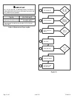
Page 18: ...ty Min Vent Length 030 045 070 090 110 135 15 ft or 5 ft plus 2 elbows or 10 ft plus 1 elbow Any approved termination may be added to the minimum length listed 030 045 070 090 110 135 Standard or Concentric See Table 3 Intake or Exhaust 1 1 2 2 2 1 2 or 3 Furnace capacity 1 Which termination 2 Which needs most elbows 3 How many 4 Desired pipe size 5 What is the altitude 6 Use Table 5 to find max p...

Page 19: ...o terminate the vent pipe outside the structure must be included in the total vent length calculation NOTE Contact your local FTC if more than 85ft of venting is needed Table 5A Maximum Allowable Intake or Exhaust Vent Length in Feet Standard Termination at Elevation 2 001 10 000 ft Number of 90 Elbows Used 2 Pipe 2 1 2 Pipe 3 Pipe Capacity Capacity Capacity 030 045 070 090 110 135 030 045 070 090...

Page 20: ...ed to terminate the vent pipe outside the structure must be included in the total vent length calculation NOTE Contact your local FTC if more than 85ft of venting is needed Table 5C Maximum Allowable Intake or Exhaust Vent Length in Feet Concentric Termination at Elevation 2 001 10 000 ft Number of 90 Elbows Used 2 Pipe 2 1 2 Pipe 3 Pipe Capacity Capacity Capacity 030 045 070 090 110 135 030 045 0...

Page 21: ...rminate the vent pipe outside the structure must be included in the total vent length calculation NOTE Contact your local FTC if more than 85ft of venting is needed Table 6A Maximum Allowable Exhaust Vent Lengths With Furnace Installed in a Closet or Basement Using Ventilated Attic or Crawl Space For Intake Air in Feet Standard Termination at Elevation 2 001 10 000 ft Number of 90 Elbows Used 2 Pi...

Page 22: ...ON 1 1 2 2 6 MINIMUM Figure 25 TYPICAL EXHAUST PIPE CONNECTIONS IN HORIZONTAL DIRECT OR NON DIRECT VENT APPLICATIONS RIGHT HAND DISCHARGE SHOWN SIDE VIEW 45 MAX 45 MAX 2 2 2 2 or 2 12 max EXHAUST TRANSITION 3 2 2 EXHAUST TRANSITION 1 1 2 2 2 EXHAUST or NOTE 1 1 2 Vent Pipe Diameter Allowed Only on 030 045 070 Units DO NOT transition from larger to smaller pipe in horizontal runs of exhaust pipe EX...

Page 23: ...talled in either direct vent or non direct vent applications In non direct vent applications when intake air will be drawn into the furnace from the surrounding space the indoor air quality must be considered and guidelines listed in Combustion Dilution and Ventilation Air section must be followed Follow the next two steps when installing the unit in Direct Vent applications where combustion air i...

Page 24: ...ing or a platform Ensure that the intake air inlet will not be obstructed by loose insulation or other items that may clog the debris screen 2 If intake air is drawn from a ventilated attic Figure 31 or ventilated crawlspace Figure 32 the exhaust vent length must not exceed those listed in Table 5D If 3 diameter pipe is used reduce to 2 diameter pipe at the termination point to accommodate the deb...

Page 25: ...are must be taken to maintain protective coatings over building materials prolonged exposure to exhaust condensate can destroy protective coatings It is recommended that the exhaust outlet not be located within 6 feet 1 8 m of a condensing unit because the condensate can damage the painted coating NOTE See Table 6A through Table 6B for maximum allowed exhaust pipe length without insulation in unco...

Page 26: ...N A 2 1 2 in N A N A 1 N A 7 N A 15 N A 22 N A N A N A 3 in N A N A N A N A 2 2 10 10 16 16 13 13 1 Refer to 99 Minimum Design Temperature table provided in the current edition of the ASHRAE Fundamentals Handbook 2 Poly Propylene vent pipe PP by Duravent and Centrotherm 3 Vent length in table is equivalent length Each elbow is equivalent to 5ft of straight pipe and should be included when measurin...

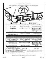
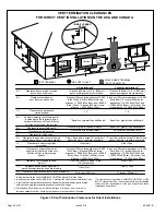
Page 27: ...rty Clearance under veranda porch deck or balcony 12 Equal to or greater than soffit depth 3 feet 9m 12 3 feet 9m within a height 15 feet 4 5m above the meter regulator assembly 3 feet 9m 6 inches 152mm for appliances 10 000 Btuh 3kw 12 inches 305mm for appliances 10 000 Btuh 3kw and 100 000 Btuh 30kw 36 inches 9m for appliances 100 000 Btuh 30kw 3 feet 9m above if within 10 feet 3m horizontally 6...

Page 28: ...6 inches 152mm for appliances 10 000 pliances 10 000 Btuh 3kw and 50 000 pliances 50 000 Btuh 15kw 6 inches 152mm for appliances 10 000 Btuh 3kw 12 inches 305mm for appliances 10 000 Btuh 3kw and 100 000 Btuh 30kw 36 inches 9m for appliances 100 000 Btuh 30kw 3 feet 9m above if within 10 feet 3m horizontally 6 feet 1 8m 7 feet 2 1m 12 inches 305mm 1 In accordance with the current ANSI Z223 1 NFPA ...

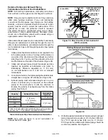
Page 29: ... 38 2 Intake and exhaust pipes should be placed as close together as possible at termination end refer to illustrations Minimum separation is 3 76 mm on roof terminations and 6 152 mm on sidewall terminations 3 On roof terminations the intake piping should terminate straight down using two 90 elbows see Figure 36 4 Exhaust piping must terminate straight out or up as shown A reducer may be required...

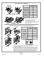
Page 30: ...ance above grade or average snow accumulation B Horizontal separation between intake and exhaust C Minimum from end of exhaust to inlet of intake D Exhaust pipe length E Wall support distance from top of each pipe intake exhaust 12 305 mm Min 12 305 mm Min 6 152 mm Min 24 610 mm Max 9 227 mm Min 12 305 mm Min 16 405 mm Max 6 152 mm Max 6 152 mm Min 24 610 mm Max 9 227 mm Min 12 305 mm Min 20 508 m...

Page 31: ...SIZE TO TERMINATION 1 1 2 38mm accelerator provided on 71M80 44W92 kits for 045 and 070 models 12 305mm INTAKE AIR EXHAUST VENT Figure 43 Direct Vent Concentric Wall Termination 71M80 69M29 OR 60L46 US 44W92 or 44W93 Canada 12 305mm Min above grade or average snow accumulation INTAKE AIR INTAKE AIR INTAKE AIR OUTSIDE WALL GRADE CLAMP Not Furnished FIELD PROVIDED REDUCER MAY BE REQUIRED TO ADAPT DI...

Page 32: ...xhaust piping must be run up a sidewall to position above snow accumulation or other obstructions piping must be supported every 24 610 mm as shown in Figure 47 When exhaust piping must be run up an outside wall any reduction in exhaust pipe size must be done after the final elbow SIZE TERMINATION PER EXHAUST PIPE TERMINATION SIZE REDUCTION TABLE Use wall support every 24 610 mm Use two supports o...

Page 33: ...Termination Drain Trap assembled Figure 49 Kit 51W18 USA 15Z70 Canada Parts Identification and Assembly Exhaust from Furnace To Termination Exhaust from Furnace To Termination Kit 51W18 is shown Figure 50 Crawl Space Vent Pipe Drain Trap Assembled Incorrectly Figure 51 Upflow or Downflow Furnace with Exhaust through Crawl Space KIT 51W18 USA Basement Floor To Termination 1 2 PVC to Code Approved D...

Page 34: ...nd Figure 56 show the furnace and evaporator coil using a separate drain If necessary the condensate line from the furnace and evaporator coil can drain together See Figure 57 and Figure 58 Upflow furnace Figure 53 In upflow furnace applications the field provided vent must be a minimum 1 to a maximum 2 length above the condensate drain outlet connection Any length above 2 may result in a flooded ...

Page 35: ...ing from furnace must slope down a minimum of 1 4 per ft toward trap Figure 54 Condensate Trap with Optional Overflow Switch When combining the furnace and evaporator coil drains together the A C condensate drain outlet must be vented to relieve pressure in order for the furnace pressure switch to operate properly WARNING ...

Page 36: ...e must slope down a minimum of 1 4 per ft toward trap Figure 56 Unit with Cooling Coil Using Separate Drain Figure 57 Evaporator Coil Using a Common Drain Figure 58 Evaporator Coil Using a Common Drain Piping from furnace and evaporator coil must slope down a minimum 1 4 per ft toward trap ...

Page 37: ...508297 01 Page 37 of 57 Issue 2219 Figure 59 Trap Drain Assembly Using 1 2 PVC or 3 4 PVC ...

Page 38: ...condensate 5 A 1 8 N P T plugged tap or pressure post is located on the gas valve to facilitate test gauge connection See Figure 60 6 In some localities codes may require installation of a manual main shut off valve and union furnished by installer external to the unit Union must be of the ground joint type Compounds used on threaded joints of gas piping must be resistant to the actions of liquifi...

Page 39: ...Upflow Application Left Side Piping Standard DRIP LEG MANUAL MAIN SHUT OFF VALVE AUTOMATIC GAS VALVE with manual shut off valve Gas Valve Horizontal Applications Possible Gas Piping Configurations NOTE BLACK IRON PIPE ONLY TO BE ROUTED INSIDE OF CABINET FIELD PROVIDED AND INSTALLED GROUND JOINT UNION DRIP LEG MANUAL MAIN SHUT OFF VALVE Horizontal Application Right Side Air Discharge Gas Valve GROU...

Page 40: ... 16 42 530 15 01 490 13 87 460 13 03 430 12 18 400 11 33 1 1 2 38 1 1 610 40 894 2100 59 46 460 41 34 1180 33 41 990 28 03 900 25 48 810 22 94 750 21 24 690 19 54 650 18 41 620 17 56 2 50 8 2 067 52 502 3950 111 85 2750 77 87 2200 62 30 1900 53 80 1680 47 57 1520 43 04 1400 39 64 1300 36 81 1220 34 55 1150 32 56 2 1 2 63 5 2 469 67 713 6300 178 39 4350 123 17 3520 99 67 3000 84 95 2650 75 04 2400 ...

Page 41: ...o make sure the wires will be long enough for servicing at a later date Make sure that thermostat wire is long enough to facilitate future removal of blower for service Complete the wiring connections to the equipment Use the provided unit wiring diagram and the field wiring diagram shown in Figure 66 Use 18 gauge wire or larger that is suitable for Class II rating for thermostat connections Elect...

Page 42: ...when there is no cooling or heating demand See Table 20 for allowable continuous circulation speeds 2 When the furnace is running in the heating mode the indoor blower will run on the heating speed 3 When there is a cooling demand the indoor blower will run on the cooling speed Generator Use Voltage Requirements The furnace requires 120 volts 10 Range 108 volts to 132 volts The furnace operates at...

Page 43: ...508297 01 Page 43 of 57 Issue 2219 030 B08 045 B12 070 B12 090 C16 110 C20 135 D20 Figure 67 Typical Wiring Diagram ...

Page 44: ...217 03 Control Red LED Flash Code2 Diagnostic Codes Status of Furnace Off No power to control or control hardware fault detected On Board Fault Detected Fast Heartbeat3 Call for Heat Burner Operation Slow Heartbeat1 Normal Operation Idle Continuous Fan or Cool 1 Flash2 Reverse Line Voltage Polarity or Phasing of 120V power 2 Flashes2 Improper earth ground 3 Flashes2 Burner failed to light or lost ...

Page 45: ...nuous Fan Speed From Indoor Blower Motor 24VAC PARK 3 Terminals For Unused Motor Speed Taps FS Flame Sensor Electrode 120VAC 24V COM Common 24VAC Table 12 Terminal Designations Applicable to 103217 03 and 107163 01 Controls Unit Start Up FOR YOUR SAFETY READ BEFORE OPERATING Do not use this furnace if any part has been underwater A flood damaged furnace is extremely dangerous Attempts to use the f...

Page 46: ...for the combustion air inducer to stop At this point the trap should be primed with sufficient water to ensure proper condensate drain operation If you do not follow these instructions exactly a fire or explosion may result causing property damage personal injury or death WARNING Gas Valve Operation See Figure 70 1 STOP Read the safety information at the beginning of this section 2 Set the thermos...

Page 47: ...alve to facilitate test gauge connection See Figure 70 Check gas line pressure with unit firing at maximum rate Low pressure may result in erratic operation or underfire High pressure can result in permanent damage to gas valve or overfire On multiple unit installations each unit should be checked separately with and without other units operating Supply pressure must fall within range listed in Ta...

Page 48: ...0 7 500 ft 0 2 286m 7 501 10 000 ft 2 286 3 048 m Natural to LP Propane High Altitude Natural Burner Orifice Kit High Altitude LP Propane Burner Orifice Kit 030 17H63 14C90 17H66 045 11K49 73W37 11K44 070 090 110 135 Pressure switch is factory set No adjustment necessary All models use the factory installed pressure switch from 0 4500 feet 0 1370 m Table 16 Burner Orifice Conversion Kits at Varyin...

Page 49: ... 2 Visually inspect the venting system for proper size and horizontal pitch Determine there is no blockage or restriction leakage corrosion or other deficiencies which could cause an unsafe condition 3 To the extent that it is practical close all building doors and windows and all doors between the space in which the appliances connected to the venting system are located and other spaces of the bu...

Page 50: ...that the blower is de energized Longer off delay settings provide lower return air temperatures shorter settings provide higher return air temperatures See Figure 71 Ignition Control 107163 01 The heat fan on time of 30 seconds is not adjustable The heat fan off delay amount of time that the blower operates after the heat demand has been satisfied may be adjusted by changing the two position dip s...

Page 51: ...315 385 1145 285 1020 230 735 130 665 115 0 60 1245 375 1110 295 980 240 685 140 620 125 0 70 N A N A 1070 305 940 250 640 145 575 135 0 80 N A N A 1020 310 905 260 600 155 530 140 NOTE All air is measured external to unit without filter filter not furnished field provided 3 Disconnect existing speed tap at control board speed terminal NOTE Termination of any unused motor leads must be insulated 4...

Page 52: ...20 Performance Less Filter External Static Pressure in w c Air Volume Watts at Various Blower Speeds Bottom Return Air Side Return Air with Optional Return Air Base Return Air from Both Sides or Return Air from Bottom and One Side Single Side Return Air Air volumes in bold require field fabricated transition to accommodate 20 x 25 x 1 in air filter in order to maintain proper air velocity High Med...

Page 53: ...744 1920 565 1690 404 1505 305 2200 978 2030 757 1850 569 1675 408 1475 308 0 40 2275 974 2070 763 1885 576 1665 419 1475 323 2175 990 2015 774 1845 584 1640 427 1450 326 0 50 2230 986 2055 779 1845 593 1620 433 1435 330 2145 989 2010 783 1820 603 1605 446 1410 332 0 60 2195 988 2030 796 1810 614 1590 451 1385 348 2125 980 1990 809 1785 618 1580 455 1375 351 0 70 2125 961 1985 806 1780 626 1545 46...

Page 54: ...y to empty condensate water 3 Remove the clean out cap from the condensate trap and empty water Inspect the trap then reinstall the clean out cap Cleaning Heat Exchanger If cleaning the heat exchanger becomes necessary follow the below procedures and refer to Figure 1 when disassembling unit Use papers or protective covering in front of furnace while removing heat exchanger assembly 1 Turn off ele...

Page 55: ...the 2 pin plug to the wire harness 38 Reconnect drain tubes between flue collar and cold end header box 39 Secure burner assembly to vestibule panel using four existing screws Burners are self aligning to center of clam shells 40 Reconnect gas supply line to gas valve 41 Reconnect flame rollout switch wires 42 Reconnect sensor wire and reconnect 2 pin plug from ignitor 43 Reconnect wires to gas va...

Page 56: ...s Problems detected during the inspection may make it necessary to temporarily shut down the furnace until the items can be repaired or replaced Instruct the homeowners to pay attention to their furnace Situations can arise between annual furnace inspections that may result in unsafe operation For instance items innocently stored next to the furnace may obstruct the combustion air supply This coul...

Page 57: ...m height of eight 8 feet above grade directly in line with the exhaust vent terminal for the horizontally vented gas fueled heating appliance or equipment The sign shall read in print size no less than one half 1 2 inch in size GAS VENT DIRECTLY BELOW KEEP CLEAR OF ALL OBSTRUCTIONS 4 INSPECTION The state or local gas inspector of the side wall horizontally vented gas fueled equipment shall not app...

Reviews: