


508298-01
Page 8 of 55
Issue 2219
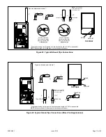
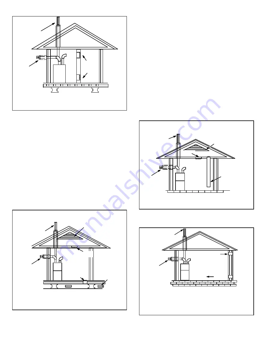
Figure 4.
Equipment in Confined Space - All Air from
Inside
OPENINGS
(To Adjacent
Unconfined
Space)
NOTE :
Each opening shall have a free area of at least one square inch
per 1,000 Btu (645 mm
2
per .29 kW) per hour of the total input rating of
all equipment in the enclosure, but not less than 100 square inches
(64516 mm
2
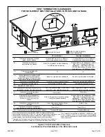
ROOF TERMINATED
EXHAUST PIPE
SIDE WALL
TERMINATED
EXHAUST PIPE
(ALTERNATE
LOCATION)
FURNACE
).
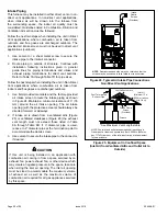
Air from Outside
If air from outside is brought in for combustion and
ventilation, the confined space shall be provided with two
permanent openings. One opening shall be within 12” (305
mm) of the top of the enclosure and one within 12” (305 mm)
of the bottom. These openings must communicate directly
or by ducts with the outdoors or spaces (crawl or attic) that
freely communicate with the outdoors or indirectly through
vertical ducts. Each opening shall have a minimum free
area of 1 square inch per 4,000 Btu (645 mm² per .59 kW)
per hour of the total input rating of all equipment in the
enclosure (see Figure 5 and Figure 6). It is also permissible
to bring air for combustion from a ventilated attic (Figure 8)
or ventilated crawl space (Figure 9).
(Inlet Air from Crawl Space and Outlet Air to Ventilated Attic)
NOTE
: The inlet and outlet air openings shall each have a free area
of at least one square inch per 4,000 Btu (645 mm
2
per 1.17 kW) per
hour of the total input rating of all equipment in the enclosure.
OUTLET
AIR
INLET
AIR
VENTILATION
LOUVERS
(For unheated
crawl space)
FURNACE
ROOF TERMINATED
EXHAUST PIPE
VENTILATION LOUVERS
(Each end of attic)
SIDE WALL
TERMINATED
EXHAUST PIPE
(ALTERNATE
LOCATION)
Figure 5.
Equipment in Confined Space - All Air from
Outside
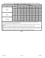
When communicating with the outdoors through horizontal
ducts, each opening shall have a minimum free area of 1
square inch (645 mm²) per 2,000 Btu (.56 kW) per hour of
the total input rating of all equipment in the enclosure. See
When ducts are used, they shall be of the same cross-
sectional area as the free area of the openings to which
they connect. The minimum dimension of rectangular
air ducts shall be no less than 3 inches (75 mm). In
calculating free area, the blocking effect of louvers, grilles,
or screens must be considered. If the design and free area
of protective covering is not known for calculating the size
opening required, it may be assumed that wood louvers
will have 20 to 25 percent free area and metal louvers and
grilles will have 60 to 75 percent free area. Louvers and
grilles must be fixed in the open position or interlocked
with the equipment so that they are opened automatically
during equipment operation.
Figure 6.
Equipment in Confined Space - All Air from
Outside
(All Air Through Ventilated Attic)
NOTE
: The inlet and outlet air openings shall each have a free area of
at least one square inch per 4,000 Btu (645 mm
2
per 1.17 kW) per hour
of the total input rating of all equipment in the enclosure.
OUTLET
AIR
VENTILATION LOUVERS
(Each end of attic)
INLET AIR
(Ends 12" above
bottom)
ROOF TERMINATED
EXHAUST PIPE
SIDE WALL
TERMINATED
EXHAUST PIPE
(ALTERNATE
LOCATION)
FURNACE
Figure 7.
Equipment in Confined Space - all Air from
Outside
OUTLET AIR
INLET AIR
NOTE
: Each air duct opening shall have a free area of at least one
square inch per 2,000 Btu (645 mm
2
per .59 kW) per hour of the total
input rating of all equipment in the enclosure. If the equipment room
is located against an outside wall and the air openings communi-
cate directly with the outdoors, each opening shall have a free area
of at least 1 square inch per 4,000 Btu (645 mm
2
per 1.17 kW) per
hour of the total input rating of all other equipment in the enclosure.
ROOF TERMINATED
EXHAUST PIPE
SIDE WALL
TERMINATED
EXHAUST PIPE
(ALTERNATE
LOCATION)
FURNACE
Summary of Contents for A96DF1E
Page 32: ...508298 01 Page 32 of 55 Issue 2219 Figure 50 Trap Drain Assembly Using 1 2 PVC or 3 4 PVC ...
Page 51: ...508298 01 Page 51 of 55 Issue 2219 Troubleshooting Heating Sequence of Operation ...
Page 52: ...508298 01 Page 52 of 55 Issue 2219 Troubleshooting Heating Sequence of Operation continued ...
Page 53: ...508298 01 Page 53 of 55 Issue 2219 Troubleshooting Cooling Sequence of Operation ...
Page 54: ...508298 01 Page 54 of 55 Issue 2219 Troubleshooting Continuous Fan Sequence of Operation ...