3
4
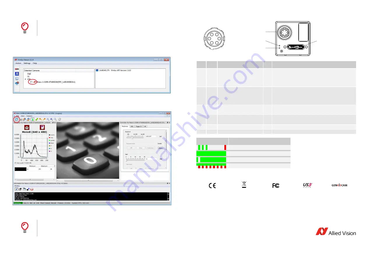
Acquiring images
1.
Connect your USB camera to your PC via USB 3.0 cable.
2.
Start
Vimba Viewer
. For instructions on Vimba Viewer, see
Vimba Quickstart Guide
provided with the Vimba
download.
3.
Select the camera in
Vimba Viewer
.
The main window opens.
4.
Start acquisition to acquire the first images with your USB camera.
Using third-party software
Camera I/Os and LEDs
Standards conformity
Contacting Allied Vision
Troubleshooting
To find solutions for unexpected events, see Chapter
Troubleshooting
in the
Mako U Technical
Manual
.
Using the camera with third-party software
Allied Vision USB cameras comply with USB3 Vision V1.0.1 standard. They can be used with
every third-party software that complies with the USB3 Vision standard.
Pin
Line
Signal
<->
Level
1
0
GPIO 1
non-isolated, programmable
I/O
U
in
(low) = 0 to 0.8 VDC
U
in
(high) = 2 to 24 VDC
U
out
(low) = 0 to 1.0 VDC
U
out
(high) = 3.3 to 24 VDC @ max. 25 mA (open collector)
2
1
GPIO 2
non-isolated, programmable
I/O
U
in
(low) = 0 to 0.8 VDC
U
in
(high) = 2 to 24 VDC
U
out
(low) = 0 to 1.0 VDC
U
out
(high) = 3.3 to 24 VDC @ max. 25 mA (open collector)
3
2
In 1
opto-isolated
In
U
in
(low) = 0 to 1.0 VDC
U
in
(high) = 3 to 24 VDC
4
3
Out 1
opto-isolated, open collector
Out U
out
(low) = 0.3 to 2 VDC
U
out
(high) = 3 to 24 VDC @ max. 25 mA (open collector)
5
---
Isolated GND for isolated I/O
---
---
6
---
GND for GPIOs
---
---
LED signal pattern
Status
Camera startup
Power on
Command or image traffic
Camera busy
CE, RoHS
WEEE
FCC
USB3 Vision
GenICam
For ordering and general information
https://www.alliedvision.com/contact
[email protected]
Support
Telephone
EMEA: +49 36428-677-0
The Americas: +1 978-225-2030
Asia-Pacific: +65 6634-9027
China: +86 (21) 64861133
1
2
3
4
5
6
6-pin I/O connector
Status LED (red)
Status LED (green)
USB 3.0 Micro-B connector


