AT-TS90-TR 10Base-T Switch With 100Base-T Access
13
5.
Once the AT-TS90TR is installed, plug the AC power cord into the AC
power connector on the front of the chassis. Plug the other end of the
power cord into a three-prong grounded outlet.
Stand-alone Mounting
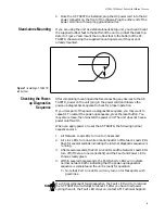
If you are using the unit as a stand-alone desk top unit, you should mount
the supplied rubber feet to the bottom of the unit to protect the desk top.
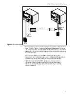
Refer to Figure 7 and mount the 4 rubber feet to the bottom of the AT-
TS90TR chassis using the supplied mounting screws, if they are not
already mounted.
Checking the Power-
up Diagnostics
Sequence
After completing mounting and before connecting any devices to the AT-
TS90TR, power on the unit (plug in the power cord) and observe the
power-up diagnostics sequence to check for proper operation.
If you miss part of the power-up diagnostics sequence, you may want to
repeat it. To restart the power-up sequence, press the reset button. You
may also remove, then reinstall the power cord. The unit does not have a
power on/off switch.
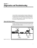
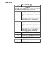
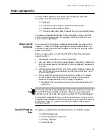
When you apply power or reset the AT-TS90TR, the following normal
sequence occurs:
1.
All Network Load LEDs turn on for one second.
2.
All Link LEDs turn on while a random pattern of Network Load LEDs
flash for several seconds indicating the internal diagnostic sequence is
running.
3.
After several seconds, the Port Link LEDs and the Network Load LEDs
turn off (if there are no connections) and the Fault and Power LEDs
show a steady green.
4.
Within several more seconds, the Port Activity LEDs will indicate
normal network traffic indicating that the power-up diagnostics
sequence is complete and the unit is ready for operation.
❑
Note that Port Link LEDs will only turn on for those ports with
good links.
If a critical component fails diagnostics, the Fault LED will turn red and
the AT-TS90TR will attempt to reboot. If, after you have tried power
cycling the unit, the Fault LED stays on, contact ATI Technical Support.
Figure 7: Installing AT-TS90TR
rubber feet
Note


