


Chapter 2: Managing Switch
74
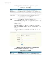
Chain Settings
Figure 52. L2 Switching > X-Ring Pro > X-Ring Pro Groups > Chain
Setting
The following table describes the items in Figure 52.
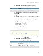
Couple Settings
Figure 53. L2 Switching > X-Ring Pro > X-Ring Pro Groups > Couple
Setting
The following table describes the items in Figure 53.
The
Information
settings in the ensuing table are informational only: Ring
ID, Mode, Operation State, Port 1, Forwarding State, Port 2, Forwarding
State and
Delete
(click to delete the desired Ring ID).
Table 49. Chain Setting
Item
Description
Chain Ring ID
Enter a number to specifies a ranging from 1 to 255 to identify a given
X-Ring group.
Role
Click the drop-down menu to designate the Role.
Head Port
Click the drop-down menu to designate the head port.
Member Port
Click the drop-down menu to designate the member port.
Add
Click
Add
to save the values and update the screen.
Table 50. Couple Setting
Item
Description
Couple Ring ID
Enter a number to specifies a ranging from 1 to 255 to identify a given
X-Ring group.
Port
Enter the port to assign to define the couple setting.
Master Ring ID
Click the drop-down menu to designate the master ring.
Add
Click
Add
to save the values and update the screen.
Summary of Contents for IS230-10GP
Page 1: ...613 002603 Rev B IS230 10GP Industrial Ethernet Layer 2 Switch Web User Guide ...
Page 7: ...Contents 8 ...
Page 11: ...Figures 12 ...
Page 15: ...Tables 16 ...
Page 19: ...Preface 20 ...


