Hardware Installation
10
5.
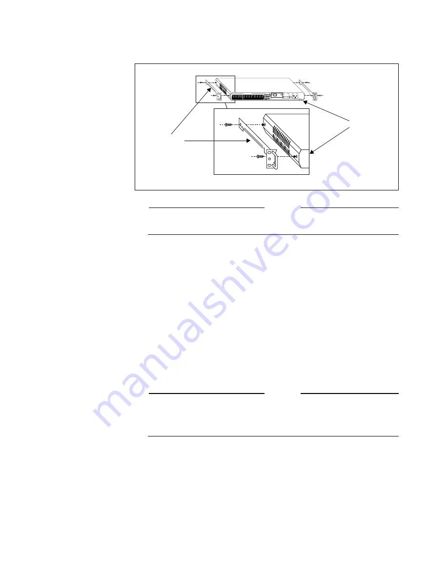
Attach the chassis guide/handle assembly to each side of the module,
using the screws provided with the chassis. See Figure 7.
Attention
Figure 7 shows a sample guide assembly only; some chassis models use a
different type of guide assembly.
6.
Make sure the chassis guide handles are aligned with the front (i.e.,
connector side) of the module, as shown in Figure 7.
7.
If necessary, remove the blank faceplate/air-dam assembly from the
slot in which you will be installing the module.
8.
Align the guide rails on either side of the module with the grooves in
the chassis slot.
9.
Slide the module along the chassis guide in the chassis, but do not seat
it in the chassis backplane connector.
10. Plug in the newly installed module’s power cord.
11. Check to see that the Power indicator illuminates.
12. Seat the module carefully and firmly in the chassis backplane.
Attention
When using the hot swapping method to insert or remove hub modules, you
must be sure that the power cord on each unit is plugged in. To enable hot
swapping, you must disconnect the module from the backplane before you
unplug the power cord.
13. Attach the module to the chassis, using the screws provided with the
chassis.
14. Connect your data cables to the hub and the network.
15. Check the Link indicators.
If one or more of the ports on the module are transferring data, the
Activity and Receive indicators will illuminate.
Figure 7: Attaching Chassis
Guides
AUI
10 BASE-T
RS-232
TERMINAL PORT
POWER
STATUS
MASTER
POWER
FAULT
APPLIQUÉ PORT
3612TR
CentreCOM
TM
IEEE 802.3/ETHERNET 10BASE2
MULTIPORT HUB / REPEATER
with Network Management
LINK
1 2 3 4 5 6 7 8
1
2
3
4
5
6
7
8
9
10
11
12
X
X
X
X
X
X
X
X
X
X
X
X
2
4
12
10
6
8
1
3
11
9
5
7
PORT ACTIVITY
10 BASE T NETWORK PORTS
No Link
Link
Receiving
Indicator OFF
Indicator ON
Indicator FLASHING
PORT STATUS
INDICATOR STATUS
Front of
Chassis
guide handle
module


