background image

Chapter 2: Installation

26

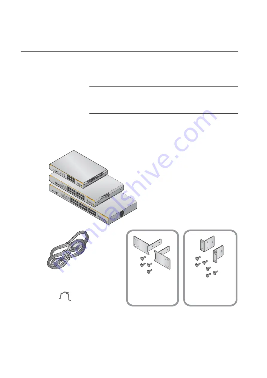
Unpacking the Switch

To unpack the switch, perform the following procedure:

1. Remove all of the components from the shipping package.

Note

Store the packaging material in a safe location. You must use the 
original shipping material if you need to return the unit to Allied 
Telesis.

2. Place the switch on a level, secure surface.

3. In addition to an AT-x210-9GT, AT-x210-16GT, or AT-x210-24GT 

switch, verify that the shipping container includes the following items:

1 Power Cable (1.8m)

AT-x210-16GT/AT-x210-24GT


1 x 19” rack mount kit

1 Power cable hook


AT-x210-16GT


2 Brackets
4 Bracket screws

(

M3×6mm pan head screws

)


AT-x210-24GT


2 Brackets
6 Bracket screws

(

M4×6mm countesunk screws

)

AT-x210-9GT

AT-x210-16GT

AT-x210-24GT

5

7

6

8

9

11

13

15R

10

12

14

16R

17

19

21

23R

18

20

22

24R

15

16

23

24

2

4

6

8

RS-232

FA

ULT

ST

ANDBY

SE

LECT

1

3

5

7

9

11

15

R

17

15

16

23

24

SP

EED

MODE

MO

DE

L/A

LINK /         

ACT

L/A

LINK /         

ACT

SFP

1

3

5

7

2

4

6

8

9

11

13

15R

10

12

14

16R

17

19

21

23R

18

20

22

24R

AT-x210-24GT

Gigabit

 Eth

er

net Switc

15

16

23

24

L/A

2

4

6

8

10

12

14

16R

18

20

22

24

R

MO

DE

L/A

MO

DE

CONS

OLE

RS-232

FA

ULT

ST

ANDBY

RESET

POWE

R

SE

LECT

1

3

5

7

9

11

13

15R

17

19

21

23R

15

16

23

24

SPEED

DU

PLEX

MODE

MO

DE

SPEED /

 D

UPLEX


L/A

LINK /         

ACT

L/A

LINK /        

 ACT

SF

P

CLA

SS

 1

LASE

R PR

OD

UCT

1

3

5

7

2

4

6

8

9

11

13

15R

10

12

14

16R

FA

ULT

ST

ANDBY

RE

SET

POWE

R

CONS

OLE

RS-23

2

SE

LEC

T SPEED

DUPLE

X

2

4

6

8

10

12

14

16R

1

3

5

7

9

11

13

15R

L/

A

MODE

L/A

MODE

15

16

15

16

AT-x210-16GT

Giga

bit Ethe

rnet Sw

itch

MOD

E

SPEED / DUPLEX  


L/A

LIN

K /         

ACT

MODE

L/A

LIN

K /


ACT

SFP

CLAS

S 1

LAS

ER 

PROD

UCT

1

3

5

7

2

4

6

8

FA

UL

T

ST

AND

BY

RESE

T

PO

WER

CO

NSOLE

RS-232

MODE

SPEED

DUPLEX

SE

LECT

2

4

6

8

1

3

5

7

L/A

MOD

E

L/A

MOD

E

9

AT-x210-9GT

Gigab

it Ethe

rne

t Switch

CLAS

S 1

LA

SER

 PRO

DU

CT

MO

DE

SP

EE

D / DU

PLE

X   


L/A

LINK 

/     

    ACT

L/A

LINK 

/  


   ACT

SF

P

1 Console Cable (2m)

Summary of Contents for AT-x210 Series

Page 1: ... MODE SPEED DUPLEX L A LINK ACT L A LINK ACT SFP CLASS 1 LASER PRODUCT 1 3 5 7 2 4 6 8 9 11 13 15R 10 12 14 16R FAULT STANDBY RESET POWER CONSOLE RS 232 SELECT SPEED DUPLEX 2 4 6 8 10 12 14 16R 1 3 5 7 9 11 13 15R L A MODE L A MODE 15 16 15 16 AT x210 16GT Gigabit Ethernet Switch MODE SPEED DUPLEX L A LINK ACT MODE L A LINK ACT SFP CLASS 1 LASER PRODUCT 1 3 5 7 2 4 6 8 FAULT STANDBY RESET POWER CO...

Page 2: ...respective owners Allied Telesis Inc reserves the right to make changes in specifications and other information contained in this document without prior written notice The information provided herein is subject to change without notice In no event shall Allied Telesis Inc be liable for any incidental special indirect or consequential damages whatsoever including but not limited to lost profits ari...

Page 3: ...equipment is operated in a commercial environment This equipment generates uses and can radiate radio frequency energy and if not installed and used in accordance with this instruction manual may cause harmful interference to radio communications Operation of this equipment in a residential area is likely to cause harmful interference in which case the user will be required to correct the interfer...

Page 4: ... Safety Statements Important The indicates that a translation of the safety statement is available in a PDF document titled Translated Safety Statements posted on the Allied Telesis website at www alliedtelesis com ...

Page 5: ...ity LEDs 15 SFP LEDs 17 Power Supply 19 Chapter 2 Installation Reviewing Safety Precautions 22 Selecting a Site for the Switch 24 Cable Specifications 25 Unpacking the Switch 26 Installing the Switch on a Table or a Desktop 27 Installing the Switch in an Equipment Rack 28 Installing Optional SFP Transceivers 35 Cabling the Switch 39 Powering On the Switch 41 Monitoring the Initialization Processes...

Page 6: ...Contents iv ...

Page 7: ...bracket positioned for an AT x210 9GT 30 Figure 20 Mounting an AT x210 16GT Switch in an Equipment Rack 31 Figure 21 Fitting rack mount handles to the brackets for an AT x210 9GT 32 Figure 22 Fitting brackets to the mounting for an AT x210 9GT 32 Figure 23 Attaching cable tray brackets for an AT x210 9GT 33 Figure 24 Mounting an AT x210 9GT Switch in an Equipment Rack 33 Figure 25 Mounting an AT x...

Page 8: ...List of Figures vi ...

Page 9: ...nd AT x210 24GT LINK ACT and SPEED DUPLEX LED Descriptions 17 Table 6 SFP Link Activity LED Functional Descriptions 18 Table 7 Twisted Pair Cabling and Distances 25 Table 8 Chassis Dimensions 52 Table 9 Chassis Weight 52 Table 10 Environmental Specifications 52 Table 11 Power Specifications 53 Table 12 Safety and Electromagnetic Emissions Certifications 53 Table 13 MDI Pin Signals 10Base T or 100B...

Page 10: ...List of Tables viii ...

Page 11: ...lation Guide 1 Preface This guide contains the installation instructions for the AT x210 9GT AT x210 16GT and AT x210 24GT Gigabit Ethernet Switches This preface contains the following sections Symbol Conventions on page 2 Contacting Allied Telesis on page 3 ...

Page 12: ...tions inform you that performing or omitting a specific action may result in equipment damage or loss of data Warning Warnings inform you that performing or omitting a specific action may result in bodily injury Warning Warnings inform you that an eye and skin hazard exists due to the presence of a Class 1 laser device ...

Page 13: ... tickets learn about RMAs and contact Allied Telesis technical experts USA and EMEA phone support Select the phone number that best fits your location and customer type Hardware warranty information Learn about Allied Telesis warranties and register your product online Replacement Services Submit a Return Merchandise Authorization RMA request via our interactive support center Documentation View t...

Page 14: ...4 ...

Page 15: ...vides descriptions of the AT x210 9GT AT x210 16GT and AT x210 24GT Gigabit Ethernet Switches and contains the following sections Features on page 6 Package Contents on page 8 Front and Back Panels on page 9 Management Software on page 11 Twisted Pair Ports on page 12 LEDs on page 13 Power Supply on page 19 ...

Page 16: ...ll duplex operation IEEE 802 3x Back Pressure in 10Base T 100Base TX half duplex operation IEEE803 3z 1000Base T Flow Control Support for Jumbo frames up to 10KB RJ 45 connectors SFP Slots All three switches support both 100Base FX and 1000Base SX LX transceivers The switches support either two or four slots for SFPs One SFP slot on the AT x210 9GT Switch Two SFP slots on the AT x210 16GT Switch F...

Page 17: ...owing way Mounted on a Desk or tabletop The AT x210 16GT and AT x210 24GT switches can be installed in the following ways Rack mounted in a19 inch equipment rack Mounted on a Desk or tabletop Wall mounted Power Conservation The AT x210 9GT AT x210 16GT and AT x210 24GT switches have the following power conservation features High efficiency power supply Power scaling based on traffic loads on ports...

Page 18: ...6R 17 19 21 23R 18 20 22 24R AT x21 0 24 GT Gig abit Eth ern et Swi tch 15 16 23 24 L A 2 4 6 8 10 12 14 16R 18 20 22 24R MODE L A MODE CO NSO LE RS 232 FAU LT STA NDB Y RES ET POW ER SEL ECT 1 3 5 7 9 11 13 15R 17 19 21 23R 15 16 23 24 SPE ED DUP LEX MO DE MODE SPE ED DUP LEX L A LINK ACT L A LINK ACT SFP CLASS 1 LASER PRODU CT 1 3 5 7 2 4 6 8 9 11 13 15R 10 12 14 16R FAU LT STA NDB Y RES ET POW ...

Page 19: ...9 21 23R 18 20 22 24R AT x210 24GT Gigabit Ethernet Switch 15 16 23 24 L A 2 4 6 8 10 12 14 16R 18 20 22 24R MODE L A MODE CONSOLE RS 232 FAULT STANDBY RESET POWER SELECT 1 3 5 7 9 11 13 15R 17 19 21 23R 15 16 23 24 SPEED DUPLEX MODE MODE SPEED DUPLEX L A LINK ACT L A LINK ACT SFP CLASS 1 LASER PRODUCT 1 3 5 7 2 4 6 8 9 11 13 15R 10 12 14 16R FAULT STANDBY RESET POWER CONSOLE RS 232 SELECT SPEED D...

Page 20: ...he front panels of the AT x210 9GT AT x210 16GT and AT x210 24GT Gigabit Ethernet Switches Figure 4 AT x210 9GT AT x210 16GT and AT x210 24GT Back Panels 1 3 5 2 4 6 FAULT STANDBY RESET POWER CONSOLE RS 232 SELECT SPEED DUPLEX 2 4 6 8 10 12 14 16R 1 3 5 7 9 11 13 15R L A MODE L A MODE MODE SPEED DUPLEX L A LINK ACT MODE 15 16 15 AT x21 Gigabit Ethern L A LINK ACT SFP MODE LED Toggle button AT x210...

Page 21: ...aphical User Interface for in band over the network management Refer to the AlliedWare Plus Software Reference for x210 Series Switches In the unlikely event that the management software becomes corrupted or damaged on the switch you can download the software from the Allied Telesis corporate web site and reinstall it on the switch For instructions on how to install new management software see the...

Page 22: ...feet For 10 Mbps operation the ports require Category 3 or better 100 ohm shielded or unshielded twisted pair cabling For 100 or 1000 Mbps operation the ports require Category 5 or Enhanced Category 5 5E 100 ohm shielded or unshielded twisted pair cabling The ports feature auto MDI which automatically configures the ports as MDI or MDI X This feature allows you to use straight through twisted pair...

Page 23: ...h See Figure 5 Figure 5 POWER LED on AT x210 9GT Table 1 describes the POWER LED for the AT x210 9GT switch Table 1 AT x210 9GT POWER LED Functional Descriptions LED State Description POWER Off Indicates either the switch is not receiving AC power or the AC input power is operating outside the normal range Steady Green The switch is receiving AC input power and is operating normally FAULT STANDBY ...

Page 24: ...0 16GT and AT x210 24GT STANDBY LED Functional Descriptions LED State Description FAULT Off The switch is receiving AC input power and is operating normally 6 flashes in 2 seconds Flashing indicates the switch is overheating Contact Allied Telesis for support and advice Steady Green Indicates the system is experiencing failure LED State Description STANDBY Off STANDBY is not supported The LED is n...

Page 25: ...nk Activity LINK ACT Off The port has not established a link with a network device or the ecofriendly feature is enabled with the MODE LED button to turn off the front panel LEDs Use the MODE LED button to turn off the front panel LEDs and conserve electricity when you are not monitoring the switch Blinking Green The port is transmitting or receiving network packets Steady Green The port has estab...

Page 26: ...ivity LEDs The AT x210 24GT switch has two LEDs per port to indicate port s link activity duplex and speed status See Figure 10 Figure 10 AT x210 24GT Link Activity Speed Port LED 2 4 6 8 10 12 14 16R 1 3 5 7 9 11 13 15R L A MODE L A MODE MODE SPEED DUPLEX L A LINK ACT Speed and Link Activity LINK ACT L A 2 4 6 8 10 12 14 16R 18 20 22 24R MODE L A MODE 1 3 5 7 9 11 13 15R 17 19 21 23R MODE SPEED D...

Page 27: ...ature is enabled with the MODE LED button to turn off the front panel LEDs Use the MODE LED button to turn off the front panel LEDs and conserve electricity when you are not monitoring the switch Blinking Green The port is transmitting or receiving network packets Steady Green The port has established a link with a network device and is active Speed Duplex SPEED DUPLEX Off The maximum operating sp...

Page 28: ...re is enabled with the MODE LED button to turn off the front panel LEDs Use the MODE LED button to turn off the front panel LEDs and conserve electricity when you are not monitoring the switch Blinking Green The SFP transceiver is transmitting or receiving network packets Activity Steady Green The SFP transceiver has established a link with a network device but is not transmitting or receiving net...

Page 29: ...witch has an internal power supply with a single AC power supply socket on the back panel To power the switch on or off connect or disconnect the power cord provided with the switch A power cord is supplied with the switch Note For the power requirements see the Power Specifications on page 53 ...

Page 30: ...Chapter 1 Overview 20 ...

Page 31: ... Selecting a Site for the Switch on page 24 Cable Specifications on page 25 Unpacking the Switch on page 26 Installing the Switch on a Table or a Desktop on page 27 Installing the Switch in an Equipment Rack on page 28 Installing Optional SFP Transceivers on page 35 Cabling the Switch on page 39 Powering On the Switch on page 41 Monitoring the Initialization Processes on page 43 ...

Page 32: ...re connecting or disconnecting the cables E1 Warning Do not work on equipment or cables during periods of lightning activity E2 Warning Power cord is used as a disconnection device To de energize equipment disconnect the power cord E3 Warning Class I Equipment This equipment must be earthed The power plug must be connected to a properly wired earth ground socket outlet An improperly wired socket o...

Page 33: ...dition is not created due to uneven mechanical loading E25 If installed in a closed or multi unit rack assembly the operating ambient temperature of the rack environment may be greater than the room ambient temperature Therefore consideration should be given to installing the equipment in an environment compatible with the manufacturer s maximum rated ambient temperature Tmra E35 Caution Installat...

Page 34: ...let for the switch should be located near the unit and should be easily accessible The site should provide for easy access to the ports on the front of the switch This will make it easier for you to connect and disconnect cables as well as view the switch s LEDs Air flow around the unit and through its vents on the side and rear should not be restricted so that the switch can maintain adequate coo...

Page 35: ...e switch Table 7 Twisted Pair Cabling and Distances Speed Type of Cable Maximum Operating Distance 10 Mbps Standard TIA EIA 568 B compliant Category 3 or better shielded or unshielded cabling with 100 ohm impedance and a frequency of 16 MHz 100 m 328 ft 100 Mbps Standard TIA EIA 568 A compliant Category 5 or TIA EIA 568 B compliant Enhanced Category 5 Cat 5e shielded or unshielded cabling with 100...

Page 36: ...DB Y SEL ECT 1 3 5 7 9 11 15R 17 15 16 23 24 SPE ED MO DE MODE L A LINK ACT L A LINK ACT SFP 1 3 5 7 2 4 6 8 9 11 13 15R 10 12 14 16R 17 19 21 23R 18 20 22 24R AT x21 0 24 GT Gig abit Eth ern et Swi tch 15 16 23 24 L A 2 4 6 8 10 12 14 16R 18 20 22 24R MODE L A MODE CO NSO LE RS 232 FAU LT STA NDB Y RES ET POW ER SEL ECT 1 3 5 7 9 11 13 15R 17 19 21 23R 15 16 23 24 SPE ED DUP LEX MO DE MODE SPE ED...

Page 37: ... front of the switches so that you can easily connect and disconnect cables and view the port LEDs The site should not expose the switches to moisture or water and the site should be a dust free environment The site should include dedicated power circuits or power conditioners to supply reliable electrical power to the network devices The rubber feet on the bottom of the switches should be left on...

Page 38: ...e bottom and turn the switch over 3 For AT x210 24GT Switches attach two rack mount brackets to the sides of the switch using the bracket screws that come with the unit Figure 16 Attaching brackets to an AT x210 24GT 1971 5 7 6 8 9 11 13 15 R 10 12 14 16 R 17 19 21 23 R 18 20 22 24 R 15 16 23 24 2 4 6 8 RS 23 2 FA UL T ST AN DB Y SE LE CT 1 3 5 7 9 11 15 R 17 15 16 23 24 SP EE D MO DE MOD E L A LI...

Page 39: ...4 2 4 6 8 RS 23 2 FA UL T ST AN DB Y SE LE CT 1 3 5 7 9 11 15 R 17 15 16 23 24 SP EE D MO DE MOD E L A LIN K AC T L A LIN K AC T SF P 1 3 5 7 2 4 6 8 9 11 13 15 R 10 12 14 16 R 17 19 21 23 R 18 20 22 24 R AT x210 24GT Giga bit Eth ern et Sw itc h 15 16 23 24 L A 2 4 6 8 10 12 14 16 R 18 20 22 24 R MO DE L A MO DE CO NS OL E RS 23 2 FA UL T ST AN DB Y RE SE T PO WE R SE LE CT 1 3 5 7 9 11 13 15 R 1...

Page 40: ... 16GT Figure 19 Close up showing a bracket positioned for an AT x210 9GT 1 3 5 7 2 4 6 8 9 11 13 15 R 10 12 14 16 R FA UL T ST AN DB Y RE SE T PO WER CO NS OL E RS 232 SE LE CT SP EE D DU PL EX 2 4 6 8 10 12 14 16 R 1 3 5 7 9 11 13 15 R L A MO DE L A MO DE 15 16 15 16 AT x210 16GT Giga bit Ethe rnet Sw itc h MO DE SP EE D DU PL EX L A LIN K AC T MOD E L A LIN K AC T SF P CLA SS 1 LAS ER PRO DUC T ...

Page 41: ... the switch as shown in Figure 20 Figure 20 Mounting an AT x210 16GT Switch in an Equipment Rack 1 3 5 7 2 4 6 8 9 11 13 15 R 10 12 14 16 R FA UL T ST AN DB Y RE SE T PO WER CO NS OL E RS 232 SE LE CT SP EE D DU PL EX 2 4 6 8 10 12 14 16 R 1 3 5 7 9 11 13 15 R L A MO DE L A MO DE 15 16 15 16 AT x210 16GT Giga bit Ethe rnet Sw itc h MOD E SP EE D DU PL EX L A LIN K AC T MOD E L A LIN K AC T SF P CL...

Page 42: ...ng rack mount handles to the brackets for an AT x210 9GT 8 After fitting the rack mount handles to the brackets using the supplied M3x6mm pan head screws as shown about in Figure 21 fit these brackets with handles to the mounting for AT x210 9GT switches using the supplied M4x6mm countersunk screws as shown below in Figure 22 Figure 22 Fitting brackets to the mounting for an AT x210 9GT ...

Page 43: ... equipment rack as shown below in Figure 24 using the screws from the rubber feet after removing these screws as shown earlier in Figure 15 Figure 24 Mounting an AT x210 9GT Switch in an Equipment Rack 1 3 5 7 2 4 6 8 FA UL T ST AN DB Y RE SE T PO W ER CO NS OL E RS 2 32 MOD E SP EE D DU PL EX SE LE CT 2 4 6 8 1 3 5 7 L A MO DE L A MO DE 9 AT x210 9GT Gi ga bit Et he rn et Sw itc h CLA SS 1 LAS ER...

Page 44: ...in an Equipment Rack 12 Secure cables to the cable tray fitted earlier as shown in Figure 26 Figure 26 Securing cables to the cable tray for an AT x210 9GT 1 3 5 7 2 4 6 8 FA UL T ST AN DB Y RE SE T PO WE R CO NS OL E RS 23 2 MO DE SP EE D DU PL EX SE LE CT 2 4 6 8 1 3 5 7 L A MOD E L A MOD E 9 AT x 210 9 GT Gig ab it Eth ern et Sw itc h CLAS S 1 LASE R PROD UCT MOD E SP EE D DU PL EX L A LIN K AC...

Page 45: ...ways install the transceiver before connecting the fiber optic cables to it 1 Remove the transceiver from its shipping container and store the packaging material in a safe location Warning An SFP transceiver can be damaged by static electricity Be sure to observe all standard electrostatic discharge ESD precautions such as wearing an antistatic wrist strap to avoid damaging the transceiver 2 Remov...

Page 46: ...n in Figure 28 Figure 28 Inserting the SFP on an AT x210 24GT 5 For an AT x210 16GT Switch gently slide the transceiver into the SFP slot until it clicks into place as shown in Figure 29 Figure 29 Inserting the SFP on an AT x210 16GT 1981 R R 15R 16R 15 16 15 16 AT x210 16GT Gigabit Ethernet Switch L A LINK ACT SFP CLASS 1 LASER PRODUCT ...

Page 47: ...itioning the SFP Handle in the Upright Position 7 Eject SFP transceivers as shown in Figure 31 First lower the SFP Transceiver Handle then gently remove the SFP Transceiver Figure 31 Ejecting an SFP transceiver after lowering the SFP Handle to the Downwards Position 8 Repeat steps 2 through 6 to install additional SFP transceivers 1983 R R SFP Transceiver Handle 15R 16R 15 16 15 16 AT x210 16GT Gi...

Page 48: ... optic cable is not installed or when storing the SFP When you do remove the plug keep it for future use Note Unnecessary removal and insertion of an SFP can lead to premature failure For information on the cable specifications of the SFP consult the documentation shipped with the SFP 9 Go to Cabling the Switch on page 39 ...

Page 49: ... of the ports is auto MDI MDI X The default setting is appropriate for switch ports that are connected to 10 100Base TX network devices that also support auto MDI MDI X The default auto MDI MDI X setting is not appropriate for switch ports that are connected to 10 100Base TX network devices that do not support auto MDI MDI X and have a fixed wiring configuration For switch ports connected to those...

Page 50: ...to Negotiation for duplex modes The default duplex mode setting for the ports is Auto Negotiation This setting is appropriate for ports connected to network devices that also support Auto Negotiation for duplex modes The default duplex mode setting of Auto Negotiation is not appropriate for ports connected to network devices that do not support Auto Negotiation and have a fixed duplex mode You sho...

Page 51: ...ower connector as shown in Figure 32 on the back of an AT x210 16GT Switch Figure 32 Lifting the AC Power Cable Hook on an AT x210 16GT Switch 2 Plug the power cord into the AC power connector as shown in Figure 33 on the back of an AT x210 16GT Switch Figure 33 Plugging in the AC Power Cord on an AT x210 16GT Switch 3 Plug the other end of the power cord into a wall outlet Power cable hook Power ...

Page 52: ...outlet shall be installed near the equipment and shall be easily accessible E5 4 Verify that the POWER LED is green If the LED is OFF see Chapter 3 Troubleshooting on page 47 The switch is now powered on and ready for network operations For information on how to manage the switch see the following manual AlliedWare Plus Software Reference for x210 Series Switches ...

Page 53: ... Figure 34 Switch Initialization Messages Bootloader 2 0 10 loaded Press Ctrl B for the Boot Menu Reading filesystem Loading flash x210 5 4 3 rel Verifying release OK Booting Starting base first OK Mounting virtual filesystems OK ______________ ____ ______ _ __ ______ ______ ____ ______ ____ ____________ Allied Telesis Inc AlliedWare Plus TM v5 4 3 Current release filename x210 5 4 3 rel Original ...

Page 54: ...ting base modules OK Received event modules done Received event board inserted Received event hardware done Starting network startup OK Starting network stackd OK Starting network election timeout OK Received event network enabled Initializing HA processes openhpid hostd cntrd nsm auth epsr hsl imiproxyd irdpd lldpd loopprot mstp rmon sflowd imi lacp Received event network initialized Assigning Ac...

Page 55: ...ntinued Assigning Active Workload to HA processes hsl nsm rmond sflowd vrrpd irdpd lacpd lldpd loopprotd mstpd authd epsrd imi imiproxyd Received event network activated Loading default configuration Warning flash default cfg does not exist loading factory defaults done Received event network configured awplus login ...

Page 56: ...Chapter 2 Installation 46 ...

Page 57: ...n Problem 2 A twisted pair port on the switch is connected to a network device but the port s LINK ACT LED is off Solutions The port is unable to establish a link to a network device Try the following Verify that the network device connected to the twisted pair port is powered on and is operating properly Verify that the twisted pair cable is securely connected to the port on the media converter c...

Page 58: ...s is to eliminate the possibility that the port is connected to the wrong remote network device such as a powered off device Try connecting another network device to the fiber optic port using a different cable If the port is able to establish a link then the problem is with the cable or with the other network device Use the switch s management software to verify that the port is enabled If the re...

Page 59: ...between the port and the network device is intermittent Try the following Connect another network device with a different cable to the port If the Link LED remains steady on then the problem is with the original cable or the network device If the problem is with an SFP transceiver check that the transceiver is fully inserted in the slot ...

Page 60: ...Chapter 3 Troubleshooting 50 ...

Page 61: ...AT x210 9GT AT x210 16GT and AT x210 24GT Switches Installation Guide 51 Appendix A Technical Specifications ...

Page 62: ... 26 in x 1 73 in AT x210 24GT 440 mm x 210 mm x 44 mm 17 32 in x 8 26 in x 1 73 in Table 9 Chassis Weight Model W x D x H mm in AT x210 9GT 1 4 kg 3 08 lbs AT x210 16GT 2 0 kg 4 41 lbs AT x210 24GT 2 7 kg 5 95 lbs Table 10 Environmental Specifications Operating Temperature 0 C to 40 C 32 F to 104 F Storage Temperature 20 C to 60 C 4 F to 140 F Operating Humidity 5 to 80 non condensing Storage Humi...

Page 63: ...le 12 Safety and Electromagnetic Emissions Certifications RFI Emissions EN 55022 2010 EN 61000 3 2 2006 A1 2009 A2 2009 EN 61000 3 3 2008 EN 62233 2008 EN 62311 2008 FCC Class A FCC Part 15 47 CFR 15 ICES 003 VCCI A VCCI B 2004 108 EC EMC Directive Electrical Safety C TICK CE 2006 95 EC Low Voltage Directive EN 60950 1 2006 A11 2009 A1 2010 A12 2011 IEC 60950 1 ed 2 UL 60950 CULUS Environmental Co...

Page 64: ... RJ 45 Connector and Port Pin Layout Table 13 lists the RJ 45 pin signals when a twisted pair port is operating in the MDI configuration Table 14 lists the RJ 45 port pin signals when a twisted pair port is operating in the MDI X configuration Table 13 MDI Pin Signals 10Base T or 100Base TX Pin Signal 1 TX 2 TX 3 RX 6 RX Table 14 MDI X Pin Signals 10Base T or 100Base TX Pin Signal 1 RX 2 RX 3 TX 6...

Page 65: ...ble 15 lists the RJ 45 connector pins and their signals when a 1000Base TX port is operating at 1000 Mbps Table 15 RJ 45 1000Base T Connector Pinouts Pin Pair Signal 1 1 TX and RX 2 1 TX and RX 3 2 TX and RX 4 3 TX and RX 5 3 TX and RX 6 2 TX and RX 7 4 TX and RX 8 4 TX and RX ...

Page 66: ...Appendix A Technical Specifications 56 ...

Reviews: