background image

Chapter 1: Overview

26

LEDs

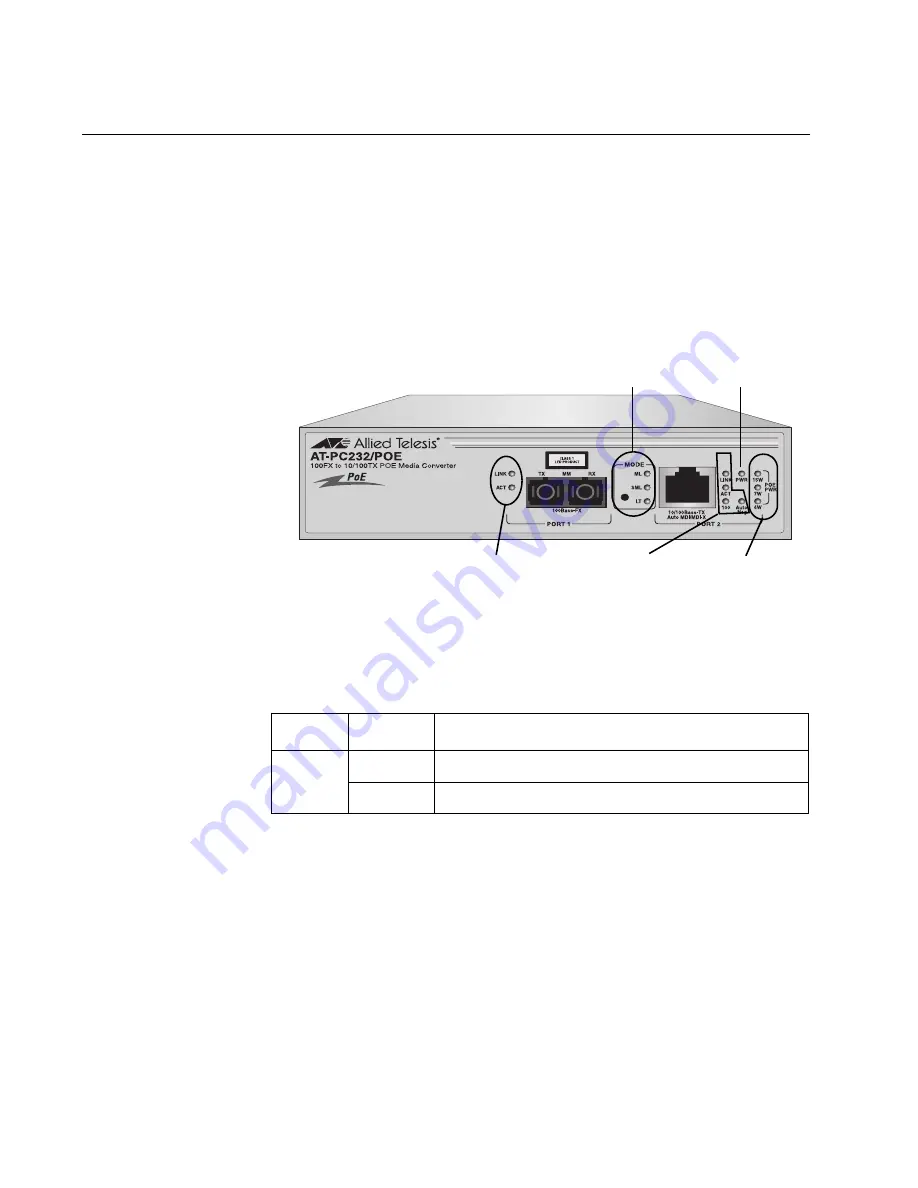
The LEDs on the AT-PC232/POE Media Converter, are shown in Figure 3 
and are described in the following sections:

“Power LED” on page 26

“10/100Base-TX Twisted Pair Port LEDs” on page 27

“100Base-FX Fiber Optic Port LEDs” on page 27

“Operating Mode LEDs” on page 28

“PoE PWR LEDs” on page 28

Figure 3. LEDs on the AT-PC232/POE Media Converter

Power LED

The function of the PWR LED is defined in Table 3.

1356

OPERATING MODE 

POWER STATUS

LED

LEDs

PWR LEDs

100BASE-FX PORT

LEDs

LEDs

10/100Base-TX PORT

PoE

Table 3. System Status LED

LED

Color

Description

PWR

Green

Indicates that the unit power is ON.

Off

Indicates that the converter power is OFF.

Summary of Contents for AT-PC232/POE

Page 1: ...613 001030 Rev A Fast Ethernet Media Converter AT PC232 POE Installation Guide ...

Page 2: ...ve owners Allied Telesis Inc reserves the right to make changes in specifications and other information contained in this document without prior written notice The information provided herein is subject to change without notice In no event shall Allied Telesis Inc be liable for any incidental special indirect or consequential damages whatsoever including but not limited to lost profits arising out...

Page 3: ...ns may cause harmful interference to radio or television reception which can be determined by turning the equipment off and on The user is encouraged to try to correct the interference by one or more of the following measures Reorient or relocate the receiving antenna Increase the separation between the equipment and the receiver Connect the equipment into an outlet on a circuit different from tha...

Page 4: ...s Important The indicates that a translation of the safety statement is available in a PDF document titled Translated Safety Statements 613 000990 posted on the Allied Telesis website at www alliedtelesis com and on this product CD ...

Page 5: ...abling 19 Auto MDI MDI X 19 Port Pinouts 19 100Base FX Fiber Optic Port 20 Type of Connector 20 Port Speed 20 Duplex Mode 20 Maximum Distance 20 Type of Cable 20 Optical Output Power 20 Optical Receiver Sensitivity 20 Operating Modes 21 Link Test Mode 21 MissingLink Mode 21 Smart MissingLink Mode 22 Setting the Operating Mode 23 Power over Ethernet 24 Power Budgeting 25 Implementation 25 LEDs 26 P...

Page 6: ...the Fiber Optic Ports 41 Connecting to the Copper Port 42 Configuring the DIP Switches 44 Installing the Power Cord Retaining Clip 45 Applying AC Power 46 Verifying the Installation 48 Chapter 3 Troubleshooting 49 Appendix A Technical Specifications 53 Physical 53 Temperature 53 Electrical Rating 53 Agency Certifications 54 10 100Base TX Port Pinouts 54 100Base FX Port Specifications 55 Appendix B...

Page 7: ...Connecting to the RJ 45 Copper Ports 42 Figure 12 Power Cord Retaining Clip 45 Figure 13 Inserting the Retaining Clip into the Retaining Bracket 45 Figure 14 Power Cord Retaining Clip in the Up Position 46 Figure 15 Connecting the AC Power Cord 46 Figure 16 Securing the Power Cord with the Retaining Clip 47 Figure 17 RJ 45 Connector and Port Pin Layout 54 Figure 18 Ferrule in an SC Connector Plug ...

Page 8: ...Figures 8 ...

Page 9: ...r Optic Port LEDs 27 Table 6 Operating Mode LEDs 28 Table 7 PoE PWR LEDs 28 Table 8 Twisted Pair Cabling and Distance Specifications 35 Table 9 Fiber Optic Cabling and Distance Specifications 35 Table 10 DIP Switch Settings 44 Table 11 MDI Pin Signals 10 100Base TX 54 Table 12 MDI X Pin Signals 10 100Base TX 55 Table 13 100Base FX Port 1 Specifications 55 ...

Page 10: ...Tables 10 ...

Page 11: ... guide provides the hardware installation instructions for your AT PC232 POE Media Converter This preface contains the following sections Safety Symbols Used in this Document on page 12 Where to Find Web based Guides on page 13 Contacting Allied Telesis on page 14 ...

Page 12: ...es the safety symbols defined in Table 1 Table 1 Safety Symbols Symbol Meaning Description Caution Performing or omitting a specific action may result in equipment damage or loss of data Warning Performing or omitting a specific action may result in electrical shock ...

Page 13: ... Find Web based Guides The installation and user guides for all Allied Telesis products are available in portable document format PDF on our web site at www alliedtelesis com You can view the documents online or download them onto a local workstation or server ...

Page 14: ...e sender s expense To obtain an RMA number contact the Allied Telesis Technical Support group at our web site www alliedtelesis com support rma Select your country from the list displayed on the website Then select the appropriate menu tab For Sales or Corporate Information You can contact Allied Telesis for sales or corporate information at our web site www alliedtelesis com Select your country f...

Page 15: ...er over Ethernet PoE power to a Powered Device PD connected to the copper port This chapter contains the following sections Introduction on page 16 Key Features on page 17 10 100Base TX Twisted Pair Port on page 18 100Base FX Fiber Optic Port on page 20 Operating Modes on page 21 Power over Ethernet on page 24 LEDs on page 26 DIP Switches on page 29 A Few Basics about Ethernet Switching on page 30...

Page 16: ...unt use and does not require software configuration or management Figure 1 illustrates the front panel of the AT PC232 POE Media Converter Figure 1 AT PC232 POE Front Panel Figure 2 illustrates the back panel of the AT PC232 POE Media Converter Figure 2 AT PC232 POE Back Panel 1356 1 2 3 4 10 100 SPEED Mbps OFF ON AUTO NEG HALF FULL DUPLEX MODE 2 PORT 1 2 2 100 240VAC 1357 ...

Page 17: ...EE 802 3af Power over Ethernet PoE compliant Supplies up to 15 4 W of PoE power on 10 100Base TX twisted pair port Supports a maximum frame size of 1916 Bytes Transparent to IEEE802 1Q packets Supports MissingLink operating mode Supports Smart MissingLink operating mode LEDs for unit and port status Store and forward switching mode MAC address table capable of storing up to 1 000 MAC addresses Sup...

Page 18: ...a If an end node can receive or transmit data but not both simultaneously the end node is operating in what is referred to as half duplex mode If an end node can both receive and transmit data simultaneously the end node is said to be operating in full duplex mode Naturally an end node capable of operating in full duplex can handle data much faster than an end node that can only operate in half du...

Page 19: ...o MDI MDI X feature to automatically configure itself as MDI or MDI X when connected to an end node Consequently you can use a straight through twisted pair cable when connecting any network device to a port The Auto MDI MDI X feature is always enabled even when the Auto Negotiate feature is turned off and the speed and duplex mode on a port are set manually Port Pinouts For the pinouts of the por...

Page 20: ...mode You can set the duplex mode manually using the DIP switches after turning Auto Negotiation off or you can let the media converter set it automatically with Auto Negotiation turned on Maximum Distance The fiber optic port has a maximum operating distance of 2 Km 1 2 mi in full duplex mode The maximum operating distance of the port will be less if it is operating in half duplex mode Type of Cab...

Page 21: ...e link this operating mode disables the transmitter on the other port This action notifies the network device connected to the port that there is a loss of the link on the other port Without the MissingLink mode a network device connected to a port would be unaware of a loss of a link on the companion port because its link to the media converter would be unaffected To explain it another way the Mi...

Page 22: ...oss of a link on a port such as managed Fast Ethernet switches running SNMP or a spanning tree protocol Conversely the MissingLink mode will be of little value if the network devices of the media converter cannot react to a lost link In the latter scenario the Link Test mode would probably be a better operating mode for the media converter during normal network operations Furthermore Allied Telesi...

Page 23: ...erter during normal network operations of a media converter However Allied Telesis recommends limiting its use to diagnosing link failures particularly if the network devices connected to the ports are managed devices The pulsing of the transmitter on a port and the constantly changing status of a link could prove problematic for some managed devices For example the device might send a constant st...

Page 24: ...iability of your network by minimizing the impact to network operations from a power failure PoE can also simplify the installation of your network A frequent issue in selecting a location for a network device is whether there is a power source nearby This often limits equipment placement or requires the added cost and time of having additional electrical sources installed With PoE you can install...

Page 25: ...trands in the cable unused 4 5 7 and 8 The PoE standard IEEE 802 3af describes two alternative ways for delivering power to a powered device PD over twisted pair cabling Alternative A uses the same strands that carry the network traffic Alternative B uses the spare strands The PoE implementation on the AT PC232 POE Media Converter is Alternative A where power is transmitted over strands 1 2 3 and ...

Page 26: ...ic Port LEDs on page 27 Operating Mode LEDs on page 28 PoE PWR LEDs on page 28 Figure 3 LEDs on the AT PC232 POE Media Converter Power LED The function of the PWR LED is defined in Table 3 1356 OPERATING MODE POWER STATUS LED LEDs PWR LEDs 100BASE FX PORT LEDs LEDs 10 100Base TX PORT PoE Table 3 System Status LED LED Color Description PWR Green Indicates that the unit power is ON Off Indicates tha...

Page 27: ...and or receiving data packets Off Indicates that there is no activity on the port 100 Green Indicates that the port is operating at 100 Mbps OFF With the LINK LED either Green or Blinking Green Indicates that the port is operating at 10 Mbps AUTO NEG Green Indicates that Auto Negotiation is ON Off Indicates that Auto Negotiation is OFF Table 5 Fiber Optic Port LEDs LED Color Description LINK Green...

Page 28: ...er is a Powered Device PD you can use the three PoE PWR LED s to determine its class ID as defined in the IEEE802 3af PoE specification The LEDs are described in Table 7 on page 28 Table 7 PoE PWR LEDs Table 6 Operating Mode LEDs LED Color Description ML Green MissingLink mode is enabled SML Green Smart MissingLink mode is enabled LT Green Link Test mode is enabled LED Color Description 4W Green I...

Page 29: ...tches are used to manually configure the operating characteristics of the 10 100BASE TX twisted pair port Port 2 such as port speed duplex mode and Auto Negotation and the duplex mode for the 100BASE FX fiber port Port 1 For the DIP switch setting refer to Table 10 on page 44 ...

Page 30: ...ard The AT PC232 POE Media Converter supports store and forward switching at Fast Ethernet full wire speed in 100 Mbps half or full duplex mode Packets entering each port are stored in buffers Once the full packet is received the media converter will forward or discard the packet depending on its destination address and error status This ensures the only error free packets destined for another seg...

Page 31: ...he fiber cable The 10 100Base TX twisted pair ports of the media converters deliver PoE power to the twisted pair ports on the different PoE Power Devices as shown in Figure 4 Figure 4 Standalone Topology 5V 2 8A RESET TO DEFAULT LAN AT 8516F SC 100Base FX Fast Ethernet Switch FAULT MASTER PWR D C L A D C L A D C L A D C L A D C L A D C L A D C L A D C L A D C L A D C L A D C L A D C L A D C L A D...

Page 32: ...while the 100Base FX ports on the two AT PC232 POE Media Converters are directly connected to each other Note When using two AT PC232 POE Media Converters back to back you must set both AT PC232 POE Media Converters to the same mode For example the first AT PC232 POE Media Converter is set to Smart MissingLink mode so the second media converter must also be set to Smart MissingLink mode Figure 5 B...

Page 33: ... the following sections Verifying the Package Contents on page 34 Planning the Installation on page 35 Desktop Installation on page 39 Wall Mount Installation on page 40 Cabling the Ports on page 41 Configuring the DIP Switches on page 44 Installing the Power Cord Retaining Clip on page 45 Applying AC Power on page 46 Verifying the Installation on page 48 ...

Page 34: ...ms are included in your package If any item is missing or damaged contact your Allied Telesis sales representative for assistance One AT PC232 POE Media Converter One AC power cord One AC power cord retaining clip Four rubber protective feet Two anchors Two screws One documentation CD ...

Page 35: ...wer lines broadband amplifiers electrical motor and fluorescent fixtures Table 8 lists the twisted pair port cabling specifications Table 9 lists the fiber optic port cabling specifications Table 8 Twisted Pair Cabling and Distance Specifications Speed Type of Cable Maximum Operating Distance 10 Mbps Standard TIA EIA 568 B compliant Category 3 or better shielded or unshielded twisted cabling with ...

Page 36: ...cated power circuit or power conditioner to supply reliable power to the unit Reviewing the Safety Guidelines Please review the following safety guidelines before you begin to install the AT PC232 POE Media Converter Note The indicates that a translation of the safety statement is available in a PDF document titled Translated Safety Statements 613 000990 posted on the Allied Telesis website at www...

Page 37: ...nto a fiber optic port should always be observed when installing or maintaining this product L5 Warning To prevent electric shock do not remove the cover No user serviceable parts inside This unit contains hazardous voltages and should only be opened by a trained and qualified technician To avoid the possibility of electric shock disconnect electric power to the product before connecting or discon...

Page 38: ...gs should be used when addressing this concern E21 Warning Do not look directly at the fiber optic cable ends or inspect the cable ends with an optical lens E29 Warning To reduce the risk of electric shock the PoE ports on this product must not connect to cabling that is routed outside the building where this device is located E40 Caution The unit does not contain serviceable components Please ret...

Page 39: ...r from its shipping container and store the packaging material in a safe location 2 Turn the converter over and place it on a secure surface 3 Attach the four rubber feet included with the unit to the corners of the bottom of the media converter as shown in Figure 6 Figure 6 Attaching Rubber Feet Do not apply power at this time Proceed to Wall Mount Installation on page 40 1362 ...

Page 40: ...n the accessory kit To wall mount the switch perform the following procedure 1 If attached remove the rubber feet data cables and power cord from the switch 2 Select a wall location for the switch 3 Install two plastic anchors and two screws into the wall so that they are level with each other and spaced 64 mm 2 52 in apart 4 Position the switch onto the wall screws as illustrated in Figure 7 Figu...

Page 41: ...OE Media Converter perform the following procedure 1 Remove the dust cover from the fiber optic port as shown in Figure 8 on page 41 Figure 8 Removing the Dust Cover from the Fiber Optic Port 2 Connect the fiber optic cable to the port as shown in Figure 9 on page 41 Figure 9 Connecting to the Fiber Optic Ports When attaching a fiber optic cable observe the following guidelines Be sure that the ca...

Page 42: ...node and the transmitter fiber connector is connected to the receiver connector on the remote node Figure 10 SC Ports 3 Connect the other end of the optical cable to the link partner Connecting to the Copper Port To connect a twisted pair cable to Port 2 on the AT PC232 POE Media Converter perform the following procedure 1 Connect a twisted pair cable with an RJ 45 connector to the 10 100Base TX p...

Page 43: ...onverter Installation Guide 43 You can use a straight through or crossover twisted pair cable to connect any type of network device to a port on the converter 2 Connect the other end of the RJ 45 cable to the link partner ...

Page 44: ...r DIP switches to manually configure these settings If you enable Auto Negotiation be sure that the end nodes are also configured for Auto Negotiation Table 10 DIP Switch Settings DIP Switch Port Function Position Description 1 2 SPEED Mbps UP The twisted pair port operates at 10 Mbps DOWN The fiber port operates at 100 Mbps 2 1 DUPLEX UP The fiber port operates in half duplex mode DOWN The fiber ...

Page 45: ...2 Power Cord Retaining Clip 2 Install the clip on the AC power connector on the back panel of the switch With the u of the clip facing down press the sides of the clip toward the center and insert the short ends into the holes in the retaining bracket as shown in Figure 13 Figure 13 Inserting the Retaining Clip into the Retaining Bracket 1 2 3 4 10 100 SPEED Mbps OFF ON AUTO NEG HALF FULL DUPLEX M...

Page 46: ...n the Up Position 2 Plug the power cord into the AC power connector on the back panel of the unit shown in Figure 15 Figure 15 Connecting the AC Power Cord Warning Power cord is used as a disconnection device To de energize equipment disconnect the power cord E3 1 2 3 4 10 100 SPEED Mbps OFF ON AUTO NEG HALF FULL DUPLEX MODE 2 PORT 1 2 2 100 240VAC 1381 1 2 3 4 10 100 SPEED Mbps OFF ON AUTO NEG HA...

Page 47: ... Securing the Power Cord with the Retaining Clip 4 Connect the other end of the power cord to an appropriate AC power outlet For the power specifications of the media converter refer to Electrical Rating on page 53 The AT PC232 POE Media Converter is now ready for network operations 1 2 3 4 10 100 SPEED Mbps OFF ON AUTO NEG HALF FULL DUPLEX MODE 2 PORT 1 2 2 100 240VAC 1382 ...

Page 48: ...essing the Mode selector button until the LT LED is on 2 Observe the Link LEDs of the twisted pair and fiber optic ports on the media converter If the Link LEDs for both of the ports are on the ports have established links with their network devices which may already be forwarding network traffic to each other through the media converter You can either leave the unit in the Link Test mode during n...

Page 49: ... Problem 2 The Link LED for the fiber optic port is on or blinking but the Link LED for twisted pair port is off Solution The twisted pair port has not established a link with its network device Try the following Verify that the network device connected to the twisted pair port is powered on and operating properly Verify that the twisted pair cable is securely connected to the port on the media co...

Page 50: ...onverter can be found in 100Base FX Port 1 Specifications on page 55 Problem 4 The Link LEDs for the two ports are on but the network devices are unable to forward traffic to each other through the media converter Solution Try the following If the network devices are managed devices use their management firmware to determine whether they are configured and operating properly If one of the network ...

Page 51: ...he original cable or the network device Problem 7 The media converter is operating in the Smart MissingLink mode and the Link LEDs for both ports are blinking Solution This could have several possible causes This can occur when a port is connected to another media converter that also supports the Smart MissingLink mode forming a chain of media converters Media converters that support the Smart Mis...

Page 52: ...Chapter 3 Troubleshooting 52 Section II Advanced Operations ...

Page 53: ...o 104 F Storage Temperature 25 C to 70 C 13 F to 158 F Operating Humidity 5 to 90 noncondensing Storage Humidity 5 to 95 noncondensing Maximum Operating Altitude 3 048 m 10 000 ft Maximum Non Operating Altitude 4 000 m 13 100 ft Electrical Rating AC Input Supply Requirements 100 240 VAC 1 0 A maximum 50 60 Hz AC Input Power 25 Watts maximum Power over Ethernet 10 100Base TX Port 15 4 Watts Maximum...

Page 54: ...EEE 802 3u RoHS RoHS China RoHS compliant MTBF 580 000 Hrs 10 100Base TX Port Pinouts Figure 17 illustrates the pin layout to an RJ 45 connector and port Figure 1 RJ 45 Connector and Port Pin Layout Table 11 lists the RJ 45 pin signals when the twisted pair port is operating in the MDI configuration at 10 or 100 Mbps Table 1 MDI Pin Signals 10 100Base TX Pin Signal 1 TX 2 TX 3 RX 6 RX 8 8 1 1 ...

Page 55: ...0Base FX Port 1 Specifications Property Value General Maximum Distance 2 km Fiber Optic Cable 50 125 µm or 62 5 125 µm core cladding multimode fiber optic cable Transmitter Characteristics Wavelength 1310 nm Output Power Min 22 5 dBm Typical 20 3 dBm Max 14 dBm Receiver Characteristics Wavelength 1310 nm Input Power Min 31 8 dBm Typical 34 5 dBm Max Saturation 14 dBm Max Power Link Budget 9 3 dB 6...

Page 56: ...Chapter Technical Specifications 56 ...

Page 57: ...ble to the naked eye can disrupt light transmission and lead to failure of the component or of the entire system Therefore it is of utmost importance to clean all fiber optic connectors before use Figure 18 shows the ferrule in an SC connector Figure 18 Ferrule in an SC Connector Plug Figure 19 shows part of the end face of an unclean and clean ferrule Figure 19 Unclean and Clean Ferrule This appe...

Page 58: ... not use compressed air or aerosol air to clean a fiber optic connector To clean a fiber optic connector using a cartridge cleaner perform the following procedure 1 With one hand hold the cartridge cleaner and push the lever on the cleaning cartridge in the direction of the arrow to expose the cleaning surface as shown in Figure 21 on page 59 Warning Do not stare into the laser beam L2 T A P E A W...

Page 59: ...tate and place it at the top and rub downwards at least 2 times Caution Failing to pick up the ferrule tip when you reach the bottom of the cleaning surface can result in static electricity that can damage the fiber optic cable 4 If desired repeat steps 3 and 4 5 If a fiber inspection scope is available use the scope to inspect the ferrule end face to make sure that it is clean 6 Reconnect the cab...

Page 60: ...vailable from many vendors as shown in Figure 22 Stick cleaners are available in both 2 5 mm and 1 25 mm sizes for use on SC and MU connectors respectively Note NEVER use a household cotton swab and or alcohol to clean a fiber optic connector This may leave a residue on the ferrule tip Figure 22 Lint Free and Alcohol Free Swabs Note Do not use compressed air or aerosol air to clean a fiber optic c...

Page 61: ...ule tip with the swab Figure 23 Cleaning a Recessed Ferrule 2 If desired repeat step 1 3 If a fiber inspection scope is available use the scope to inspect the connector to make sure that it is clean and to check for scratches pits or other problems that may affect performance Note Always keep a dust cap on a fiber optic cable when it is not in use Note Do not touch the end face of the ferrule in t...

Page 62: ...Appendix B Cleaning Fiber Optic Connectors 62 ...

Reviews: