Allied Telesis AT-MWS1750AP Installation Manual Download Page 34

Chapter 2: Installing the AT-MWS2533AP Access Point

34

Installing the Access Point on a Celling or Wall

The AT-MWS2533AP access point can be mounted on a celling or wall.

Guidelines for

Installing the

Device on a

Celling or Wall

Review the following guidelines before installing the access point on a 
ceiling or wall:

You must provide the four self-tapping screws that secure the 
mounting base plate to the ceiling or wall.

The ceiling or wall mounting surface must be of proper material to 
accommodate the self-tapping screws, strong enough to support 
the weight of the equipment and cables. 

Connect the Ethernet cable to the access point before installing the 
access point on the ceiling or wall if connecting the Ethernet cable 
will be difficult after the access point is installed.

The AT-MWS2533AP access point can be installed on a ceiling or 
tabletop. See Figure 7.

Figure 7. Correct Ceiling or Tabletop Installation

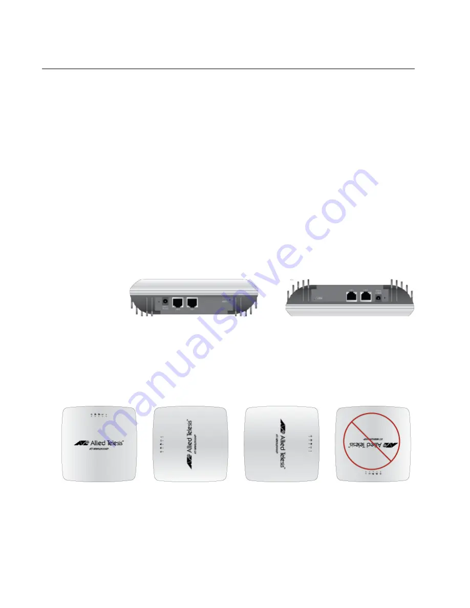
The AT-MWS2533AP access point can be mounted on the wall; 
however, installing the access point with the LAN ports facing up is 

not

 allowed. See Figure 8 for correct and incorrect wall installation 

orientations.

Figure 8. Correct and Incorrect Wall Installation

Correct Tabletop Installation

Correct Ceiling Installation

Correct

Correct

Correct

Incorrect

Summary of Contents for AT-MWS1750AP

Page 1: ...613 002418 Rev D MWS Series SIMULTANEOUS DUAL BAND WIRELESS ACCESS POINT AT MWS600AP AT MWS1750AP AT MWS2533AP Installation Guide...

Page 2: ...espective owners Allied Telesis Inc reserves the right to make changes in specifications and other information contained in this document without prior written notice The information provided herein i...

Page 3: ...if not installed and used in accordance with the instructions may cause harmful interference to radio communications However there is no guarantee that interference will not occur in a particular inst...

Page 4: ...issued by the Commission of the European Community Radiation Explore Statement This equipment complies with EU radiation exposure limits set forth for an uncontrolled environment This equipment shoul...

Page 5: ...by requiring supplier Declarations of Conformity monitoring incoming materials and maintaining manufacturing process controls Safety and Electromagnetic Emissions Certificates Standard Compliance RoHs...

Page 6: ...UL 60950 1 2nd Edition CAN CSA C22 2 No 60950 1 07 2nd Edition Translated Safety Statements Important The indicates that a translation of the safety statement is available in a PDF document titled Tr...

Page 7: ...P 23 Cable Specifications 25 Cable Requirements 25 Maximum Distance 25 Chapter 2 Installing the AT MWS2533AP Access Point 27 Reviewing Safety Precautions 28 Unpacking the AT MWS2533AP Access Point 30...

Page 8: ...s Point 46 Hard Surface Ceiling and Wall Installation 47 Ceiling T Rail Installation 50 Connecting the Access Point with the Ethernet Cable 53 Connecting the AC Adapter 54 Appendix A Technical Specifi...

Page 9: ...tructions for the MWS Series Wireless Access Points The models included in this manual are AT MWS600AP AT MWS1750AP AT MWS2533AP This preface contains the following sections Safety Symbols Used in thi...

Page 10: ...g conventions Note Notes provide additional information Caution Cautions inform you that performing or omitting a specific action may result in equipment damage or loss of data Warning Warnings inform...

Page 11: ...tickets learn about Return Merchandise Authorizations RMAs and contact Allied Telesis technical experts USA and EMEA phone support Select the phone number that best fits your location and customer ty...

Page 12: ...Preface 12...

Page 13: ...es the hardware components of the MWS series wireless access point This chapter contains the following sections Overview on page 14 Features on page 16 LAN Port on page 18 Redundant Power Supply on pa...

Page 14: ...The MWS series access point can be installed on a ceiling wall or tabletop In addition the AT MWS600AT and AT MWS1750AP models can be installed on a ceiling T rail AT MWS600AP and AT MWS1750AP Models...

Page 15: ...The access point is illustrated in Figure 3 Figure 3 The Top Panel of the AT MWS2533AP Model The front side of the AT MWS2533AP model is illustrated in Figure 4 Figure 4 The Front Side View of the AT...

Page 16: ...100 1000Base T Ethernet port with IEEE802 3at PoE 2 4GHz 802 11b g n 2x2 MIMO support 5GHz 802 11a n 2x2 MIMO support Maximum capacity 2 4 GHz 300Mbps Maximum capacity 5 GHz 300Mbps Ceiling T rail in...

Page 17: ...city 2 4 GHz 800Mbps when using 256QAM modulation scheme Maximum capacity 5 GHz 1 7Gbps Kensington lock support Management Features The features to manage the access point are listed here Standalone S...

Page 18: ...pin RJ45 connector The port uses four pins at 10 or 100 Mbps and all eight pins at 1000 Mbps The pin assignments are listed in LAN Port on page 57 Speed The LAN port can operate at 10 100 or 1000 Mbp...

Page 19: ...port on the Ethernet switch You may not disable automatic MDIX detection For automatic MDIX detection to work properly it must also be present on the Ethernet switch The LAN port defaults to MDIX if...

Page 20: ...quipped with two PoE capable LAN ports The model can drain power through the DC jack When power from the DC jack is not available it drains through the LAN2 port when power is not available through th...

Page 21: ...C jack No redundancy 5 On The access point drains power through the LAN2 port No redundancy 6 On The access point drains power through the LAN1 port No redundancy 8 On On The access point drains power...

Page 22: ...ess power is powered ON and operating normally Off The access point is not receiving power LAN Blue A valid link is established on the port Blinking Blue Data is being transmitted received Off No link...

Page 23: ...e port at 1000Mbps Blinking Green Data is being transmitted received at 1000Mbps Amber A valid link is established on the port at 10Mbps or 100Mbps Blinking Amber Data is being transmitted received at...

Page 24: ...Fi Green The 5GHz Wi Fi interface is enabled Blinking Green Data is being transmitted received at the 5GHz frequency band Off The 5GHz Wi Fi interface is disabled Table 4 LEDs for the AT MWS2533AP Acc...

Page 25: ...maximum operating distance of 100 meters 328 feet Table 5 Twisted Pair Cable for the LAN Port Cable Type 10Mbps 100Mbps 1000Mbps PoE PoE PoE Standard TIA EIA 568 A compliant Category 5 shielded or uns...

Page 26: ...Chapter 1 Product Description 26...

Page 27: ...Unpacking the AT BRKT MWS01 Mounting Base Plate on page 31 Unpacking the AT MWS0091 AC Adapter Kit on page 32 Installing the Access Point on a Celling or Wall on page 34 Connecting the Access Point wi...

Page 28: ...ns hazardous voltages and should only be opened by a trained and qualified technician To avoid the possibility of electric shock disconnect electric power to the product before connecting or disconnec...

Page 29: ...114 Warning To prevent electric shock slide the AC power plug into the AC DC power adapter before plugging into the AC power wall receptacles E116 The following warning applies only to the AT MWS1750A...

Page 30: ...g box 2 Save the packaging material in a safe location You must use the original shipping material if you need to return the unit to Allied Telesis Note To install the AT MWS2533AP access point on a c...

Page 31: ...se plate is not included in the AT MWS2533AP access point package You must purchase the mounting base plate separately 1 Remove the AT BRKT MWS01 mounting base palate from the shipping box and verify...

Page 32: ...To unpack the AT MWS0091 AC adapter kit perform the following procedure 1 Remove all components from the shipping box Note Store the packaging material in a safe location You must use the original sh...

Page 33: ...cess Point Installation Guide 33 3 If any item is missing or damaged contact your Allied Telesis sales representative for assistance Plug for Australia APD2 AU Table 6 Components in the Shipping Box N...

Page 34: ...nough to support the weight of the equipment and cables Connect the Ethernet cable to the access point before installing the access point on the ceiling or wall if connecting the Ethernet cable will b...

Page 35: ...he Celling or Wall To install the access point on the celling or wall perform the following procedure Note Attaching the access point to the mounting base plate may not be easy once the mounting base...

Page 36: ...ling or Wall 5 Insert the two pins on the mounting base plate into the circles of the keyhole slots as shown in Figure 10 Figure 10 Aligning the Access Point with the Mounting Base Plate 6 Slide the a...

Page 37: ...lation Guide 37 Figure 11 Sliding the Access Point to Secure the Mounting Base Plate 7 Fasten the captive screw on the mounting base plate to secure the access point Figure 12 Fastening the Captive Sc...

Page 38: ...Access Point with the Ethernet Cable To connect the access point with the Ethernet cable perform the following procedure 1 Connect the RJ 45 plug into the LAN port as shown in Figure 13 Figure 13 Conn...

Page 39: ...To connect the AC adapter perform the following procedure 1 Connect the AC adapter into the DC jack on the access point as shown in Figure 14 Figure 14 Connecting the LAN Cable and Attaching the Seal...

Page 40: ...change the AC plug on the AT MWS0091 AC adapter perform the following procedure 1 Select one from the optional AC plugs See Table 6 on page 32 2 While pressing the release tab with your thumb slide th...

Page 41: ...oint Installation Guide 41 Figure 17 Attaching the AC Plug to the AC Adapter Warning To prevent electric shock slide the AC power plug into the AC DC power adapter before plugging into the AC power wa...

Page 42: ...Chapter 2 Installing the AT MWS2533AP Access Point 42...

Page 43: ...oint It contains the following sections Unpacking the AT MWS600AP or AT MWS1750AP Access Point on page 44 Installing the Access Point on page 46 Connecting the Access Point with the Ethernet Cable on...

Page 44: ...1 Remove all components from the shipping boxes Note Store the packaging material in a safe location You must use the original shipping material if you need to return the unit to Allied Telesis 2 Veri...

Page 45: ...es representative for assistance Rail clip kit 2 x Narrow rail clip 2 x Wide rail clip 2 x Spacer 2 x Short screw to attach a rail clip without the spacer or attach to the access point directly 2 x Lo...

Page 46: ...s you planned before installing the access point Once the access point is installed it may be difficult to change the cables Connect the Ethernet cable and power code to the access point before instal...

Page 47: ...base Phillips head screwdriver Pencil Note A Phillip head screwdriver and pencil are not included in the shipping box Installing the Access Point on the Hard Surface Celling or Wall To install the acc...

Page 48: ...to the access point and adjust the height of the screws where the access point can be turned to be secured to the mounting base as shown in Figure 21 Figure 21 Adjusting the Screws on the Access Poin...

Page 49: ...is installed it may be difficult to change the location 8 If you are installing the access point on the wall ensure that the orientation of the mounting base is correct 9 Using the mounting base as a...

Page 50: ...ure 26 Figure 26 Turning the Access Point to Secure to the Mounting Base Ceiling T Rail Installation To install the access point on the ceiling T rail perform the following procedure What to Prepare f...

Page 51: ...spacers to the access point using the long screws as shown in Figure 27 Figure 27 Attaching the Rail Clips and Spacers to the Access Point 4 Connect an Ethernet cable See Connecting the Access Point w...

Page 52: ...P or AT MWS1750AP Access Point 52 6 Align the rail clips on the access point to the ceiling T rail and apply force to attach the access point to the rail as shown in Figure 28 Figure 28 Attaching the...

Page 53: ...ss Point with the Ethernet Cable To connect the access point with the Ethernet cable perform the following procedure 1 Connect the RJ 45 plug into the LAN port as shown in Figure 29 Figure 29 Connecti...

Page 54: ...Connecting the AC Adapter To connect the AC adapter perform the following procedure 1 Connect the AC adapter into the DC jack on the access point as shown in Figure 30 Figure 30 Connecting the AC Ada...

Page 55: ...t AT MWS600AP 161 mm x 161 mm x38 6 3 in x 6 3in x 1 5in 280g 0 62 lb AT MWS1750AP 161 mm x 161 mm x38 6 3 in x 6 3in x 1 5in 340g 0 75 lb AT MWS2533AP 215 mm x 215 mm x 56 mm 8 5 in x 8 5 in x 2 2 in...

Page 56: ...ntal Specifications Operating Temperature of the Access Point 0 C to 40 C 32 F to 104 F Storage Temperature 20 C to 60 C 4 F to 140 F Operating Humidity 10 to 80 non condensing Storage Humidity 10 to...

Page 57: ...n the LAN Port Table 13 lists the pin signals when the port is operating in the MDI configuration at 10 or 100 Mbps Table 12 LAN Port Specifications Connector RJ45 Standards IEEE 802 3 10Base T IEEE 8...

Page 58: ...le 15 lists the pin signals when the LAN port is operating at 1000 Mbps Table 14 MDI X Pin Signals 10Base T or 100Base TX Pin Signal 1 RX 2 RX 3 TX 6 TX Table 15 1000Base T Connector Pinouts Pin Pair...

Reviews: