


Chapter 3: AT-MCF2012LC, AT-MCF2012LC/1 and AT-MCF2032SP Modules
44
Section I: Features
Link Test Mode
When a channel is set to the Link Test mode, the Link LEDs report the
current states of the connections between the ports and the local and
remote network devices. The Link LED of a port will be on when a port has
a link to its network device and it will be off when a port does not have a
link.
Refer to Table 8 for the descriptions of the states of the Link LEDs for the
twisted pair port and the fiber optic port in a channel set to the Link Test
mode.
MissingLink Mode
The ports in a channel set to this mode operate in tandem. A channel port
is not allowed to establish a link with its local or remote network device
unless its companion port in the channel can also establish a link with its
network device. As a result, the Link LEDs of the ports also work in
tandem. As described in Table 9, the Link LEDs will be on if both ports can
establish links to their network devices, and they will if off if one or both
ports cannot establish links. For more information on this operating mode,
refer to “MissingLink Mode” on page 37.
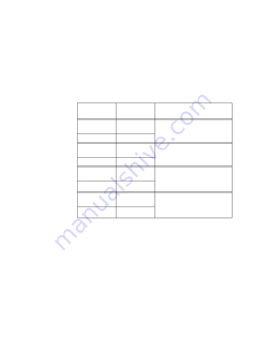
Table 8. Link LEDs in the Link Test Mode
Channel Ports
Link LED
States
Description
Twisted Pair
Port
Off
Neither port in the channel has
established a link to a network
device.
Fiber Optic Port
Off
Twisted Pair
Port
Steady Green or
Amber
Both ports in the channel have
established links to their network
devices.
Fiber Optic Port
Steady Green
Twisted Pair
Port
Steady Green or
Amber
The twisted pair port has
established a link to its network
device, but the fiber optic port has
not established a link.
Fiber Optic Port
Off
Twisted Pair
Port
Off
The fiber optic port in the channel
has established a link to a network
device, but the twisted pair port
has not established a link.
Fiber Optic Port
Steady Green
Summary of Contents for AT-MCF2000
Page 8: ...Contents 8...
Page 12: ...Tables 12...
Page 18: ...Preface 18...
Page 20: ...20 Section I Features...
Page 26: ...Chapter 1 AT MCF2000 Multi channel Media Converter Series 26 Section I Features...
Page 54: ...Chapter 3 AT MCF2012LC AT MCF2012LC 1 and AT MCF2032SP Modules 54 Section I Features...
Page 72: ...Chapter 4 AT MCF2000M Management Module 72 Section I Features...
Page 84: ...Chapter 5 AT MCF2000S Stacking Module 84 Section I Features...
Page 86: ...86 Section II Installation...
Page 90: ...Chapter 6 Reviewing the Safety Precautions 90 Section II Installation...
Page 92: ...Chapter 7 Selecting a Location 92 Section II Installation...
Page 96: ...Chapter 8 Unpacking the AT MCF2000 or AT MCF2300 Chassis 96 Section II Installation...
Page 98: ...Chapter 9 Removing the Rubber Feet 98 Section II Installation...
Page 106: ...Chapter 11 Installing the AT MCF2KFAN Module 106 Section II Installation...
Page 110: ...Chapter 12 Installing a Media Converter Module 110 Section II Installation...
Page 122: ...Chapter 15 Installing the Chassis in an Equipment Rack 122 Section II Installation...
Page 128: ...Chapter 17 Installing the SFP Modules in the AT MCF2032SP Module 128 Section II Installation...
Page 130: ...Chapter 18 Cabling the Ports on the Media Converter Module 130 Section II Installation...
Page 134: ...Chapter 19 Cabling the AT MCF2000M and AT MCF2000S Modules 134 Section II Installation...
Page 138: ...Chapter 20 Powering on the Chassis 138 Section II Installation...
Page 156: ...Chapter 23 Troubleshooting the Modules 156 Section II Installation...
Page 186: ...Appendix C Cleaning Fiber Optic Connectors 186...
Page 190: ...Index 190...


