


Chapter 1: Overview
24
FAULT LED
The FAULT LED reports any conditions on the switch that are not normal.
Table 3 describes the states of the FAULT LED.
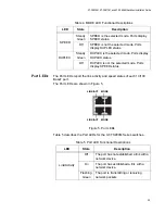
MODE LEDs
The MODE LEDs display which mode is selected on the switch: Speed or
Duplex. The mode is selected using the Mode button, located on the left
side of the front panel of the switch. For a description of the Mode button,
refer to “Mode Button” on page 28.
The MODE LEDs are located on the left side of the front panel of the
switch. See Figure 4.
Figure 4. MODE LEDs
Table 4 on page 25 describes the MODE LEDs for the AT-FS900M Series
switches.
Table 3. FAULT LED Functional Description
State
Description
Off
Normal switch operation.
Steady
Red
Abnormal system operation.
Flashing
Red
One of following:
Firmware downloading and being
written to flash memory.
DC internal power operating outside
the normal range.
Temperature out of range.
MODE LEDs
Mode Button
Summary of Contents for AT-FS909M
Page 1: ...613 001985 Rev A AT FS909M AT FS917M AT FS926M Fast Ethernet Switches Installation Guide...
Page 6: ...Contents 6...
Page 8: ...List of Figures 8...
Page 10: ...List of Tables 10...
Page 14: ...14...
Page 30: ...Chapter 1 Overview 30...
Page 50: ...Chapter 2 Installation 50...