Chapter 4: Installing the Chassis
94
Figure 48. Lowering the Locking Handle on the AT-SBxPWRSYS1-80 DC
Power Supply
8. Visually inspect the power supply to be sure that its faceplate is flush
against the front panel of the chassis and the locking handle is fully
down.
Note
Do not tighten the handle locking screw yet. You may need to
slightly lift the handle to move the plastic guard panel when you
connect the positive and negative wires.
9. If necessary, repeat this procedure to install a second power supply.
10. After installing the power supplies, go to “Installing Ethernet Line
Summary of Contents for AT-FAN08
Page 10: ...Figures 10...
Page 12: ...Tables 12...
Page 16: ...Preface 16...
Page 38: ...Chapter 1 Overview 38...
Page 60: ...Chapter 2 Virtual Chassis Stacking 60...
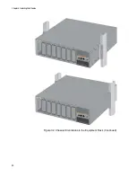
Page 82: ...Chapter 4 Installing the Chassis 82 Figure 34 Example of Adjusting the Equipment Rack Brackets...
Page 104: ...Chapter 4 Installing the Chassis 104...
Page 140: ...Chapter 5 Powering On the Chassis 140...
Page 166: ...Chapter 7 Cabling the AT XEM2 Line Card Ports 166...

