background image

AT-SBx908 GEN2 Installation Guide for Virtual Chassis Stacking

59

Planning the Stack

Here are factors to consider when planning a stack:

How many SBx908 GEN2 Chassis will be in the stack? The 
maximum is four chassis.

How many trunk links will there be between switches? The 
maximum numbers of permitted links vary by Ethernet line card 
and are listed in Table 10 on page 46.

Which ports will be the trunk links? Refer to “Stacking Guidelines” 
on page 41
.

Do all the switches have the same version of the AlliedWare Plus 
management software, preferably v5.4.8-0.2 or later? Instructions 
on how to verify this information is explained later in “Viewing the 
AlliedWare Plus Version Number” on page 149.

Do all the switches have the same optional feature licenses? 
Instructions on how to verify this information is explained later in 
“Viewing Optional Feature Licenses” on page 150.

Have you selected ID numbers, in the range of 1 to 4, for the 
switches? You can control the ID number assignments by the order 
in which you initially power on the switches, or you can have the 
switches assign the numbers automatically. Refer to “Switch ID 
Numbers” on page 57.

Summary of Contents for AT-FAN08

Page 1: ...5 4 8 0 AT SBx908 GEN2 Chassis AT XEM2 12XT Ethernet Line Card AT XEM2 12XS Ethernet Line Card AT XEM2 4QS Ethernet Line Card AT XEM2 1CQ Ethernet Line Card AT FAN08 Fan Module AT SBxPWRSYS2 AC Power...

Page 2: ...ir respective owners Allied Telesis Inc reserves the right to make changes in specifications and other information contained in this document without prior written notice The information provided here...

Page 3: ...s equipment generates uses and can radiate radio frequency energy and if not installed and used in accordance with this instruction manual may cause harmful interference to radio communications Operat...

Page 4: ...4 Translated Safety Statements Important Safety statements that have the symbol are translated into multiple languages in the Translated Safety Statements document at www alliedtelesis com support...

Page 5: ...0 Power Supplies 32 AT FAN08 Units 34 Specifying Ports in the Command Line Interface 35 Software and Hardware Releases 37 Chapter 2 Virtual Chassis Stacking 39 Overview 40 Stacking Guidelines 41 Maste...

Page 6: ...Local Management Session 145 Verifying the Switch with AlliedWare Plus Commands 148 Viewing the AlliedWare Plus Version Number 149 Viewing Optional Feature Licenses 150 Enabling the VCStack Feature 15...

Page 7: ...ng Box 71 Figure 25 Removing the Switch from the Protective Shipping Bag 71 Figure 26 Pre installed Items on the Front and Side Panels 72 Figure 27 Pre installed Items on the Rear Panel 73 Figure 28 A...

Page 8: ...inal Screws 122 Figure 79 Connecting the Positive Power Wire with a Straight Terminal 123 Figure 80 Connecting the Negative Power Wire with a Straight Terminal 124 Figure 81 Closing the Plastic Cover...

Page 9: ...Grounding Post 188 Figure 121 Lifting the Locking Handle and Removing the Power Supply 189 Figure 122 Installing the Blank Power Supply Slot Cover 190 Figure 123 Lowering the Locking Handle on the Po...

Page 10: ...Figures 10...

Page 11: ...ack Feature 151 Table 14 Example of Designating Trunk Ports 154 Table 15 AT XEM2 Line Cards and Fiber Optic Transceivers 160 Table 16 AT XEM2 Line Cards and Direct Connect Cables 163 Table 17 Product...

Page 12: ...Tables 12...

Page 13: ...w to build a virtual stack of up to four units with the Virtual Chassis Stacking VCStack feature For instructions on how to install the switch as a stand alone device refer to the AT SBx908 GEN2 Insta...

Page 14: ...tions Note Notes provide additional information Caution Cautions inform you that performing or omitting a specific action may result in equipment damage or loss of data Warning Warnings inform you tha...

Page 15: ...ickets to learn about RMAs and to contact Allied Telesis technical experts USA and EMEA phone support Select the phone number that best fits your location and customer type Hardware warranty informati...

Page 16: ...Preface 16...

Page 17: ...e Cards on page 21 AT XEM2 12XT Line Card on page 22 AT XEM2 12XS Line Card on page 24 AT XEM2 4QS Line Card on page 25 AT XEM2 1CQ Line Card on page 26 Management Panel on page 27 Power Supplies on p...

Page 18: ...line cards are listed here AT XEM2 12XT Card features 12 1Gbps 10Gbps twisted pair ports with RJ 45 connectors AT XEM2 12XS Card features 12 transceiver slots for 1Gbps SFP or 10Gbps SFP transceivers...

Page 19: ...or local management no IP address required USB 2 0 port for storing backup copies of system configuration files transferring management software among units and other management functions An eco frien...

Page 20: ...the unit is installed in the equipment rack You might bend the chassis and cause misalignment of the slots and card guides if you lift the chassis into the equipment rack without the line card slot co...

Page 21: ...ne Cards AT XEM2 12XT Line Card with 12 1Gbps or 10Gbps ports with RJ 45 connectors AT XEM2 12XS Line Card with 12 slots for 1Gbps SFP or 10Gbps SFP transceivers or 10Gbps AT SP10TW direct connect twi...

Page 22: ...speed with Auto Negotiation or manually The default is Auto Negotiation Duplex Mode Full duplex only Cabling 1Gbps Standard TIA EIA 568 B compliant Category 6 shielded cabling or better 10Gbps Standar...

Page 23: ...Off Possible causes of this state are listed here The port has not established a link with another network device The LEDs are turned off To turn on the LEDs use the eco friendly button Table 2 Link...

Page 24: ...ed separately For a list of supported transceivers refer to the AT SBx908 GEN2 Series data sheet on the Allied Telesis web site The slots have link and activity LEDs The states of the LEDs are describ...

Page 25: ...e AT QSFP1CU and AT QSFP3CU direct connect cables in lengths of 1 and 3 meters respectively The LED states for the QSFP transceiver slots on the AT XEM2 4QS Line Card are described in Table 4 Table 4...

Page 26: ...0km 6 2 mi Requires single mode fiber optic cable with a duplex LC connector The LED states for the transceiver slot on the AT XEM2 1CQ Line Card are described in Table 5 Table 5 Link and Activity Sta...

Page 27: ...ed network backup location for Allied Telesis Management Framework Store backup copies of configuration files Transfer configuration files between switches that are to have similar configurations Stor...

Page 28: ...tically with automatic MDIX detection You may disable automatic MDIX detection and set the wiring configuration manually The port is referred to as eth0 in the management software The cable requiremen...

Page 29: ...ent session must be a local management session For instructions on how to start a local management session refer to Starting a Local Management Session on page 145 or the Software Reference for Switch...

Page 30: ...to conserve electricity When the LEDs are off the overall power consumption of the switch is slightly reduced by approximately 2 watts The button controls all the port LEDs on the Ethernet line cards...

Page 31: ...s do not forward network traffic for about three minutes while they initialize the AlliedWare Plus operating system and configure their parameter settings Some network traffic may be lost Note To rese...

Page 32: ...YS2 and AT SBxPWRSYS1 80 Power Supplies Here are the power supply guidelines The AT SBxPWRSYS2 AC Power Supply uses the AC connectors on the back panel of the switch and is intended for AC environment...

Page 33: ...er supplies are installed in the PSU A and PSU B slots in the front panel of the chassis If you are installing only one power supply Allied Telesis recommends installing it in PSU A slot because that...

Page 34: ...ules in FAN A and FAN B slots on the rear panel The air flow is from the front to the back of the chassis with the fans drawing air out of the device The fan module has two fans The switch automatical...

Page 35: ...h the ID number 3 awplus enable awplus configure terminal awplus config interface port3 2 15 port3 2 17 Table 8 PORT Parameter Format Number Description Stack ID Number Designates the switch s ID numb...

Page 36: ...Chapter 1 Overview 36 For instructions on the command line interface and the PORT parameter refer to the Software Reference for AT SBx908 GEN2 Switch AlliedWare Plus Operating System...

Page 37: ...ing software and AT SBx908 GEN2 Switch are listed in Table 9 Table 9 Software and Hardware Releases Software Version Hardware v5 4 7A 1 AT SBx908 GEN2 Chassis AT XEM2 12XT Line Card AT XEM2 12XS Line...

Page 38: ...Chapter 1 Overview 38...

Page 39: ...Member Switches on page 55 Switch ID Numbers on page 57 Optional Feature Licenses on page 58 Planning the Stack on page 59 Note For more information on VCStack refer to the Stacking Introduction and...

Page 40: ...number of IP addresses you have to assign to network devices The one address gives you management access to all the units Adds feature flexibility and resiliency A stack gives you more flexibility in...

Page 41: ...ork link called a stack trunk Here are the trunk guidelines Trunk ports can be 10Gbps 40Gbps or 100Gbps There are no default trunk ports A stack can have only one trunk but as explained here a trunk c...

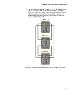
Page 42: ...is referred to as a ring because the last switch in the stack is connected to the first switch creating a loop This is the recommended configuration It adds resiliency to the stack because it enables...

Page 43: ...ng 43 You can omit the link from the last to first switches to create a linear trunk An example of a stack with three switches in a linear trunk is shown in Figure 10 This trunk topology is not recomm...

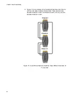
Page 44: ...creasing the number of physical links between switches The example in Figure 11 uses ports on AT XEM2 12XS Line Cards to build a stack of three switches with a trunk of three links from switch to swit...

Page 45: ...n a switch This makes it possible for trunks to continue functioning though at reduced bandwidths even if line cards with trunk ports fail The example in Figure 12 is a stack of three switches with a...

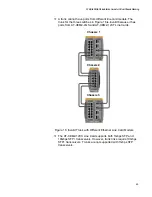
Page 46: ...ards which as listed in Table 10 can have a maximum of four trunk ports per switch The two switches have six stacking ports each making the trunk invalid To bring the example into compliance with the...

Page 47: ...e same line card or different cards in a switch so long as the cards are all the same model With stacks of three or four switches the number of physical links in the trunk has to be the same on all sw...

Page 48: ...nk because the units do not have the same number of trunk links There are two links between chassis 1 and 2 and chassis 2 and 3 but only one link between chassis 1 and 3 Figure 15 Invalid Trunk Becaus...

Page 49: ...ure 16 is invalid because it has ports from AT XEM2 4QS and AT XEM2 12XT Line Cards Figure 16 Invalid Trunk with Different Ethernet Line Card Models The AT XEM2 12XS Line Card supports both 1Gbps SFP...

Page 50: ...racks However you cannot build a trunk with both direct connect cables and fiber optic transceivers A trunk can have either one or the other but not both The example trunk of AT XEM2 12XS Line Cards i...

Page 51: ...with either direct connect cables or fiber optic transceivers but not both Figure 18 is an example of an invalid trunk on AT XEM2 4QS Line Cards because it uses both direct connect and fiber optic ca...

Page 52: ...Line Cards for a stack trunk But since the card has only one 100Gbps transceiver slot each switch has to have two cards Figure 19 is an example of a stack trunk of four switches with the line card Fi...

Page 53: ...no switch can have trunk links to more than two other chassis The trunk example in Figure 20 is invalid because chassis 1 has trunk links to all three of the other switches Figure 20 Invalid Trunk Be...

Page 54: ...termediary network devices such as media converters routers or Ethernet switches Figure 21 is an example of an invalid trunk because it has intermediary network devices in this case media converters F...

Page 55: ...master switch stops operating Selection of the Master Switch The switches of the stack designate the master switch during the initialization process that they perform whenever they are powered on or r...

Page 56: ...Stacking 56 After the stack is established and operating you may if you choose change the priority settings on the individual units and so control which switch will be the master switch after subseque...

Page 57: ...commands in the management software For further information refer to Specifying Ports in the Command Line Interface on page 35 The ID numbers are also used to identify the parameter settings that are...

Page 58: ...this product Here are the guidelines to feature licenses for a stack of SBx908 GEN2 Series switches The VCStack feature is part of the base features of the switch and does not require an optional feat...

Page 59: ...have the same version of the AlliedWare Plus management software preferably v5 4 8 0 2 or later Instructions on how to verify this information is explained later in Viewing the AlliedWare Plus Versio...

Page 60: ...Chapter 2 Virtual Chassis Stacking 60...

Page 61: ...sections Hardware Installation Overview on page 62 Reviewing Safety Precautions on page 64 Choosing a Site for the Chassis on page 69 Unpacking the Chassis on page 70 Unpacking AT SBxPWRSYS2 AC Power...

Page 62: ...ge 69 3 Unpack the hardware Unpacking the Chassis on page 70 Unpacking AT SBxPWRSYS2 AC Power Supplies on page 75 Unpacking AT SBxPWRSYS1 80 DC Power Supplies on page 76 4 Install the hardware Adjusti...

Page 63: ...l Chassis Stacking 63 4 continued Install the hardware Installing the Blank Power Supply Slot Cover on page 101 Installing the Power Cord Retaining Clips on page 103 Table 11 Hardware Installation Pro...

Page 64: ...ass 1M Laser product Warning Do not stare into the laser beam L2 Warning Do not look directly at the fiber optic ends or inspect the cable ends with an optical lens L6 Warning To prevent electric shoc...

Page 65: ...t The socket outlet shall be installed near the equipment and shall be easily accessible E5 Caution Air vents must not be blocked and must have free access to the room ambient air for cooling E6 Warni...

Page 66: ...e par une batterie de type incorrect peut provoquer un danger d explosion La remplacer uniquement par une batterie du m me type ou de type quivalent recommand e par le constructeur Les batteries doive...

Page 67: ...operation of the equipment is not compromised E36 Warning Reliable earthing of rack mounted equipment should be maintained Particular attention should be given to supply connections other than direct...

Page 68: ...nsceiver may exceed 70 C 158 F Exercise caution when removing or handling transceivers with unprotected hands E43 Warning The grounding lug on the rear panel of the chassis is for supplemental groundi...

Page 69: ...on the front and rear panels The ventilation direction is from front to back with the fans on the back panel drawing the air out of the unit The site should not expose the chassis to moisture or water...

Page 70: ...ox Figure 23 AT SBx908 Gen2 Switch Shipping Box The items in the box are listed here A Protective bag B AT SBx908 Gen2 Switch C Accessory kit To unpack the switch perform the following procedure 1 Lif...

Page 71: ...e out of the shipping box You might injure yourself or damage the device if you lift it without assistance Figure 24 Lifting the Switch from the Shipping Box 2 Remove the switch from the protective sh...

Page 72: ...n in Figure 26 Figure 26 Pre installed Items on the Front and Side Panels 4 Visually inspect the rear panel for the pre installed components shown in Figure 27 on page 73 2 Seven line card slot covers...

Page 73: ...original packaging material in the event you need to return the unit to Allied Telesis Note The product does not come with power supplies Power supplies must be ordered separately 5 Remove the accesso...

Page 74: ...unpacking the switch do one of the following To unpack the power supplies go to Unpacking AT SBxPWRSYS2 AC Power Supplies on page 75 or Unpacking AT SBxPWRSYS1 80 DC Power Supplies on page 76 Otherwi...

Page 75: ...e Shipping Box for the AT SBxPWRSYS2 AC Power Supply The tie wrap included with the power supply is not used with the AT SBx908 Gen2 chassis If any item is missing or damaged contact your Allied Teles...

Page 76: ...ms in the Shipping Box for the AT SBxPWRSYS1 80 DC Power Supply If any item is missing or damaged contact your Allied Telesis sales representative for assistance After unpacking the chassis and power...

Page 77: ...kets on page 79 Installing the Chassis in an Equipment Rack on page 83 Installing the Chassis Grounding Wire on page 84 Installing AT SBxPWRSYS2 AC Power Supplies on page 87 Installing AT SBxPWRSYS1 8...

Page 78: ...s and Material You need to provide the following tools and material to install the chassis 2 Phillips head screwdriver Eight screws for a standard 19 inch equipment rack 10 AWG stranded grounding wire...

Page 79: ...e front of the chassis with the front of the equipment rack You can re position the brackets on the sides of the chassis to have the device extend in front of the rack Figure 31 here and Figure 32 on...

Page 80: ...Chapter 4 Installing the Chassis 80 Figure 32 Chassis Orientations in the Equipment Rack Continued...

Page 81: ...1 Figure 33 Chassis Orientations in the Equipment Rack Continued To change the positions of the brackets use a 2 Phillips head screwdriver to remove them from their default positions and secure them t...

Page 82: ...Chapter 4 Installing the Chassis 82 Figure 34 Example of Adjusting the Equipment Rack Brackets...

Page 83: ...an equipment rack E28 To install the chassis perform the following procedure 1 Place the chassis on a level secure surface 2 If you want to reposition the brackets from their pre installed positions...

Page 84: ...ar panel of the chassis 2 Phillips head screwdriver not provided Crimping tool not provided 10 AWG stranded grounding wire not provided To connect the chassis to an earth ground perform the following...

Page 85: ...he Chassis 3 Insert one end of the grounding wire into the grounding lug as shown in Figure 38 and use a crimping tool to secure the wire to the grounding lug Figure 38 Attaching the Grounding Wire to...

Page 86: ...39 Installing the Grounding Lug and Wire 5 Connect the other end of the grounding wire to the building protective earth 6 Go to Installing AT SBxPWRSYS2 AC Power Supplies on page 87 or Installing AT...

Page 87: ...city Be sure to follow proper anti static precautions when installing the device Allied Telesis recommends using a properly grounded wrist strap or other personal anti static device and an anti static...

Page 88: ...3 Lift the handle on the AT SBxPWRSYS2 AC Power Supply Refer to Figure 41 Figure 41 Lifting the Locking Handle on the AT SBxPWRSYS2 Power Supply 4 Carefully align the power supply in the slot and slid...

Page 89: ...Power Supply into the Chassis 5 Gently press on the faceplate of the power supply to seat the unit on the connector on the backplane of the chassis and lower the locking handle to secure the unit in t...

Page 90: ...to be sure that its faceplate is flush against the front panel of the chassis and the locking handle is fully down 7 If necessary repeat this procedure to install a second power supply 8 After instal...

Page 91: ...ling the device Allied Telesis recommends using a properly grounded wrist strap or other personal anti static device and an anti static mat To install AT SBxPWRSYS1 80 DC Power Supplies in the chassis...

Page 92: ...4 With a 2 Phillips head screwdriver loosen the handle locking screw on the power supply as shown in Figure 45 Figure 45 Loosening the Handle locking Screw on the AT SBxPWRSYS1 80 DC Power Supply 5 L...

Page 93: ...he slot and slide it into the slot until it makes contact with the connector inside the chassis Refer to Figure 47 Figure 47 Inserting the AT SBxPWRSYS1 80 DC Power Supply 7 Gently press on the facepl...

Page 94: ...the front panel of the chassis and the locking handle is fully down Note Do not tighten the handle locking screw yet You may need to slightly lift the handle to move the plastic guard panel when you...

Page 95: ...follow proper anti static precautions when installing the device Allied Telesis recommends using a properly grounded wrist strap or other personal anti static device and an anti static mat To install...

Page 96: ...o Figure 50 Figure 50 Removing the Ethernet Line Card from the Anti static Bag 4 Position the line card with the notch on the faceplate in the upper left corner as shown in Figure 51 on page 97 and ca...

Page 97: ...Caution Do not force the card into the slot If you feel resistance remove it and try again 5 When you feel the line card make contact with the connector on the backplane of the chassis gently press on...

Page 98: ...is flush against the front panel of the chassis 7 Tighten the two captive screws on the card to secure it in the chassis Refer to Figure 53 Figure 53 Tightening the Two Captive Screws on the Ethernet...

Page 99: ...ered line card slots go to Installing the Blank Power Supply Slot Cover on page 101 If there are empty uncovered line card slots perform the following procedure To install blank slot covers perform th...

Page 100: ...alling the Chassis 100 Figure 55 Tightening the Captive Screws on a Blank Slot Cover 3 Repeat this procedure to install additional blank slot covers 4 Go to Installing the Blank Power Supply Slot Cove...

Page 101: ...ower supply is already covered go to Installing the Power Cord Retaining Clips on page 103 If a power supply slot is uncovered continue with the procedure in this section To install the bank power sup...

Page 102: ...ly Cover in the Slot 3 Lower the locking handle on the blank power supply slot cover to secure the cover in the chassis Refer to Figure 58 Figure 58 Lowering the Locking Handle on the Blank Power Supp...

Page 103: ...To install a power cord retaining clip press in the sides and insert the ends into the holes above and below the AC connector Repeat to install the second power cord retaining clip Refer to Figure 59...

Page 104: ...Chapter 4 Installing the Chassis 104...

Page 105: ...hapter contains the following procedures Verifying the Installation on page 106 Powering On AT SBxPWRSYS2 Power Supplies on page 107 Powering On AT SBxPWRSYS1 80 DC Power Supplies on page 110 Monitori...

Page 106: ...lips on the AC power connectors on the rear panel of the chassis For instructions refer to Installing the Power Cord Retaining Clips on page 103 4 Verify that the grounding lug on the back panel of th...

Page 107: ...ze equipment disconnect the power cord E3 Note Pluggable Equipment The socket outlet shall be installed near the equipment and shall be easily accessible E5 Caution If the chassis has two AT SBxPWRSYS...

Page 108: ...AC Power Cord 2 Move the retaining clip over the power cord to secure the cord to the chassis Refer to Figure 61 Figure 61 Securing the Power Cord with the Retaining Clip 3 Connect the power cord to...

Page 109: ...have 20 Amp 125 V NEMA 5 20P plugs The plugs require NEMA 5 20R receptacles Refer to Figure 22 on page 69 4 If the switch has two power supplies repeat this procedure to connect a power cord to the se...

Page 110: ...inals that come with the power supply Two 8 AWG stranded power wires not provided One 10 AWG stranded grounding wire not provided Here are the wire requirements for bare wire installation Two 8 AWG so...

Page 111: ...ircuit breaker Do not work with HOT feeds to avoid the danger of physical injury from electrical shock Always be sure that the circuit breaker is in the OFF position before connecting the wires to the...

Page 112: ...ng Terminal To attach a grounding wire with the grounding terminal provided with the power supply perform the following procedure 1 Prepare an adequate length of stranded 10 AWG grounding wire by stri...

Page 113: ...n Off switch on AT SBxPWRSYS1 80 DC Power Supply is in the Off position Refer to Figure 67 Figure 67 On Off Switch on the AT SBxPWRSYS1 80 DC Power Supply 4 Use an 8 mm wrench to remove the grounding...

Page 114: ...o the grounding post Refer to Figure 69 on page 115 Review the following before installing the grounding wire You should angle the wire to the right so that you can open the plastic window to access t...

Page 115: ...15 Figure 69 Attaching the Grounding Lug and Wire to the Grounding Post 6 Secure the grounding wire with the nut and washer removed in step 4 with an 8 mm wrench Refer to Figure 70 on page 116 Allied...

Page 116: ...ective earth Warning When installing this equipment always ensure that the power supply ground connection is installed first and disconnected last E11 Note This system will work with a positive ground...

Page 117: ...shown in Figure 71 Figure 71 Stripping the solid or Stranded Grounding Wire 2 Verify that the On Off switch on AT SBxPWRSYS1 80 DC Power Supply is in the Off position Refer to Figure 67 on page 113 3...

Page 118: ...n step 2 and an 8 mm wrench as shown in Figure 73 Allied Telesis recommends tightening the nut and washer to 26 inch lbs Figure 73 Securing the Bare Grounding Wire to the Grounding Post 6 After connec...

Page 119: ...es using bare wires Here are the procedures for wiring the positive and negative terminal block on the power supply Connecting the DC Power Wires with the Straight Terminals on page 119 Connecting the...

Page 120: ...nals See Figure 76 Figure 76 Attaching the Power Wires to the Straight Terminal Lugs 3 Verify that the On Off switch on AT SBxPWRSYS1 80 Power Supply is in the Off position Refer to Figure 67 on page...

Page 121: ...allation Guide for Virtual Chassis Stacking 121 Figure 77 Opening the Plastic Cover 5 Use a 3 Phillips head screwdriver to remove the two screws from the positive and negative terminals as shown in Fi...

Page 122: ...ositive terminal on the power supply with one of the terminal screws removed in the previous step The positive terminal is on the left You may attach the terminals with the wires either above or below...

Page 123: ...the negative power lead wire to the negative terminal on the power supply with the remaining terminal screw removed in step 5 The negative terminal is on the right You may attach the terminals with t...

Page 124: ...ed copper wire strands extending from the terminal block Any exposed wiring can conduct harmful levels of electricity to persons touching the wires E12 8 Slide the plastic cover to the left and lightl...

Page 125: ...or Virtual Chassis Stacking 125 Figure 81 Closing the Plastic Cover over the Terminal Connectors 9 With a 2 Phillips head screwdriver tighten the handle locking screw to secure the power supply to the...

Page 126: ...e switch repeat this procedure to install the second power supply 13 Turn the DC circuit breaker s on 14 Turn the On Off switch es on the AT SBxPWRSYS1 80 DC Power Supply ies to the On position See Fi...

Page 127: ...wire on the terminal block after installation E10 Note You must use stranded wires with the terminal lugs You may not use solid wires 2 Insert the power wires into the terminals included with the powe...

Page 128: ...er 5 Powering On the Chassis 128 Figure 84 Removing the Plastic Cover 5 Use a 3 Phillips head screwdriver to remove the two screws from the positive and negative terminals as shown in Figure 85 on pag...

Page 129: ...h a 3 Phillips head screwdriver connect the positive power lead wire to the positive terminal on the power supply with one of the terminal screws removed in the previous step The positive terminal is...

Page 130: ...l 7 With a 3 Phillips head screwdriver connect the negative power lead wire to the negative terminal on the power supply with the remaining terminal screw removed in step 5 The negative terminal is on...

Page 131: ...trands coming from the installed wires When this installation is done correctly there should be no exposed copper wire strands extending from the terminal block Any exposed wiring can conduct harmful...

Page 132: ...switch repeat this procedure to install the second power supply 12 Turn the DC circuit breaker s on 13 Turn the On Off switch es on the AT SBxPWRSYS1 80 Power Supply ies to the On position See Figure...

Page 133: ...the cover to the right as shown in Figure 77 on page 121 You may need to lift the locking handle slightly to access the bottom screw 3 Use a 3 Phillips head screwdriver to remove the two screws from...

Page 134: ...Bare Wire 5 Wrap the negative lead wire clockwise around the remaining terminal screw and secure the screw and wire to the negative terminal connection on the terminal block with a 3 Phillips head sc...

Page 135: ...is done correctly there should be no exposed copper wire strands extending from the terminal block Any exposed wiring can conduct harmful levels of electricity to persons touching the wires E12 6 Sli...

Page 136: ...you have two AT SBxPWRSYS1 80 DC Power Supplies for the switch repeat this procedure to install the second power supply 11 Turn the DC circuit breaker s on 12 Turn the On Off switch es on the AT SBxP...

Page 137: ...as it initializes the management software Figure 92 Switch Initialization Messages Loading flash sbx908ng braodcomdev 20170406 1 rel Verifying release OK Booting setup_system Starting base first OK M...

Page 138: ...Received event apteryx sync done Received event board inserted Starting hardware hardware done OK Received event hardware done Starting network startup OK Starting base external media OK Received eve...

Page 139: ...ized its management software go to Chapter 6 Configuring Switches for Stacking on page 141 Assigning Active Workload to HA processes hsl authd epsrd imi imiproxyd irdpd lacpd lldpd loopprotd mstpd nsm...

Page 140: ...Chapter 5 Powering On the Chassis 140...

Page 141: ...arting a Local Management Session on page 145 Verifying the Switch with AlliedWare Plus Commands on page 148 Viewing the AlliedWare Plus Version Number on page 149 Viewing Optional Feature Licenses on...

Page 142: ...Trunk ports should not be cabled yet Note Cabling trunk ports before activating the VCStack feature may result in loops in your network topology which can cause poor network performance Table 12 lists...

Page 143: ...e the trunk ports for the switch Designating Trunk Ports on page 153 STACKPORT command in port Interface modes 11 Save your changes WRITE command in the Privileged Exec mode 12 Power off the switch Po...

Page 144: ...e switch ID numbers yourself Or perform Powering On the Switches Simultaneously on page 172 to have the switches assign the numbers automatically 19 Confirm that the stack is operating correctly Verif...

Page 145: ...f the switch has an AC power supply connect the AC power cord to the power supply on the back panel and to an AC power source if the switch has two power supplies you need to power on only one of them...

Page 146: ...ion program 5 Configure the VT 100 terminal or terminal emulation program as follows Baud rate 115 200 bps Data bits 8 Parity None Stop bits 1 Flow controller None Note The port settings are for a DEC...

Page 147: ...wn in Figure 96 is displayed Figure 96 User Exec Mode Prompt Note The User Exec mode is the first level in the command mode interface For complete information on the modes and commands refer to the So...

Page 148: ...Ok status The next command SHOW CARD has to be performed from the Privileged Exec mode If you are still in the User Exec mode enter the ENABLE command to move to the Privileged Exec mode The mode prom...

Page 149: ...c mode enter either the SHOW SYSTEM or SHOW VERSION command 3 Examine the Software Version field in the information the command displays on your screen and do one of the following If the field says 54...

Page 150: ...a local management session For instructions refer to Starting a Local Management Session on page 145 2 In the Privileged Exec mode enter the SHOW LICENSE BRIEF command Figure 97 is an example Figure...

Page 151: ...tion Start a local management session on the switch For instructions refer to Starting a Local Management Session on page 145 awplus enable awplus Enter the ENABLE command to move from the User Exec m...

Page 152: ...file after you create the stack awplus reboot reboot system y n awplus Restart the switch with the REBOOT command Type Y for yes Wait three minutes for the switch to initialize its management software...

Page 153: ...from ports The commands are performed in the port Interface modes Note This procedure requires reseting the switch Some network traffic will be lost if the switch is connected to an active network He...

Page 154: ...ation mode awplus config if interface port1 2 1 port1 5 4 awplus config if Enter the INTERFACE command to move to the Interface mode of port1 2 1 and port1 5 4 awplus config if stackport awplus config...

Page 155: ...ove from the User Exec mode to the Privileged Exec mode awplus show stack detail Stack port1 2 1 status Down Stack port1 5 4 status Down Enter the SHOW STACK DETAIL command to confirm that the designa...

Page 156: ...for stacking 3 After configuring all the switches confirm that they are all powered off 4 Review the following items Do all the switches have the same version of the AlliedWare Plus operating softwar...

Page 157: ...e following procedures Cabling 1Gbps and 10Gbps Ports on AT XEM2 12XT Line Cards on page 158 Guidelines to Handling Twisted Pair or Fiber Optic Transceivers on page 159 Installing and Cabling Fiber Op...

Page 158: ...ports and the tabs should lock the connectors into place The default speed setting for the ports is Auto Negotiation This setting is appropriate for ports connected to network devices that also suppor...

Page 159: ...n AT XEM2 line cards before connecting their fiber optic cables Fiber optic transceivers are dust sensitive Always keep the plug in the optical bores when a fiber optic cable is not installed or when...

Page 160: ...nsceiver in an Ethernet line card perform the following procedure 1 Select a slot in the AT XEM2 line card for the transceiver 2 If the selected slot has a dust cover remove it 3 Remove the transceive...

Page 161: ...12XS Line Card AT XEM2 4QS Line Card Figure 101 shows an AT QSFPLR4 transceiver being installed in an AT XEM2 4QS Line Card Figure 101 Installing a Fiber Optic Transceiver in the AT XEM2 4QS Line Card...

Page 162: ...transceiver continue with the next step Otherwise repeat steps 1 to 4 to install additional transceivers 5 If the fiber optic connector on the transceiver has a dust cover remove the cover 6 Connect t...

Page 163: ...ping container and store the packaging material in a safe location 4 Orient the transceiver and slide it into the slot until it clicks into place The correct orientation depends on the line card and t...

Page 164: ...s in the AT XEM2 12XS Line Card AT XEM2 4QS line card Orient the connector on the AT QSFPCU Cable with the release tab on the left side and slide it into the slot until it clicks into place Refer to F...

Page 165: ...ther end of the cable into a compatible slot on another network device 6 Repeat this procedure to install additional direct connect cables Note To remove the connector and cable from the slot gently p...

Page 166: ...Chapter 7 Cabling the AT XEM2 Line Card Ports 166...

Page 167: ...d Verifying the Stack This chapter contains the following procedures Introduction on page 168 Powering On the Switches Sequentially on page 169 Powering On the Switches Simultaneously on page 172 Veri...

Page 168: ...e Switches Sequentially on page 169 The numbers are assigned in the order in which you power on the units If you want the switches to assign the ID numbers automatically perform Powering On the Switch...

Page 169: ...its parameter settings once it becomes part of the stack The first switch to be powered on during the initial power on sequence becomes the master switch of the stack However if you do not change the...

Page 170: ...le Equipment The socket outlet shall be installed near the equipment and shall be easily accessible E5 2 Wait three minutes for the switch to initialize its management software The switch should now b...

Page 171: ...for Virtual Chassis Stacking 171 store their ID numbers in special files in the flash memories and retain them even when you reset or power cycle the devices 6 To continue with the installation go to...

Page 172: ...uence of the stack You configured the switches for stacking as explained in Chapter 6 Configuring Switches for Stacking on page 141 The switches are connected with a stack trunk For background informa...

Page 173: ...To de energize equipment disconnect the power cord E3 Note Pluggable Equipment The socket outlet shall be installed near the equipment and shall be easily accessible E5 2 Wait four minutes for the swi...

Page 174: ...e displaying Normal operations which indicates the stacking ports are operating normally If the Operational Status field is displaying Not all stack ports are up one or more trunk ports are not cabled...

Page 175: ...ues of the switches perform the following procedure 1 Use the CONFIGURE TERMINAL command to move from the Privileged Exec mode to the Global Configuration mode Refer to Figure 106 Figure 106 Moving to...

Page 176: ...RITE command to save your change in the configuration file The switch displays the confirmation prompt in Figure 108 Figure 108 Saving the Priority Values with the WRITE Command 5 To end the managemen...

Page 177: ...s chapter contains the following procedures Replacing AT SBxPWRSYS2 AC Power Supplies on page 178 Replacing AT SBxPWRSYS1 80 DC Power Supplies on page 181 Replacing AT XEM2 Line Cards on page 192 Repl...

Page 178: ...structions refer to the Software Reference for SwitchBlade x908 Gen2 Switches Caution If you are installing the AT SBxPWRSYS2 AC Power Supply in an active operational switch you should connect the AC...

Page 179: ...and disconnect the cord Refer to Figure 110 Figure 110 Disconnecting the AC Power Cord from the Chassis 3 Lift the locking hand on the power supply Refer to Figure 111 Figure 111 Lifting the Locking...

Page 180: ...ng the AT SBxPWRSYS2 AC Power Supply 5 Do one of the following To install a new power supply refer to Installing AT SBxPWRSYS2 AC Power Supplies on page 87 for instructions If you are not installing a...

Page 181: ...he following procedure 1 Turn off the circuit breaker to the AT SBxPWRSYS1 80 DC Power Supply 2 Turn off the On Off switch on the front panel of the power supply Refer to Figure 44 on page 92 3 Use a...

Page 182: ...You may need to slightly lift the locking handle to access the bottom screw Refer to Figure 114 The plastic cover might not be present if you used the right angle terminals to connect the lead wires...

Page 183: ...GEN2 Installation Guide for Virtual Chassis Stacking 183 Figure 115 Removing the Negative Lead Wire 6 Use a 3 screwdriver to remove the positive lead wire from the terminal block Refer to Figure 116 o...

Page 184: ...Chapter 9 Replacing Modules 184 Figure 116 Removing the Positive Lead Wire from the Terminal Block 7 Reinstall the two screws on the negative and positive terminals Refer to Figure 117 on page 185...

Page 185: ...y tighten the two screws to secure it in place Refer to Figure 118 on page 186 Caution Do not over tighten the screws or you might crack or break the plastic cover The plastic cover might not be prese...

Page 186: ...Chapter 9 Replacing Modules 186 Figure 118 Closing the Plastic Cover 9 Use an 8 mm wrench to remove the grounding wire from the grounding post Refer to Figure 119 on page 187...

Page 187: ...AT SBx908 GEN2 Installation Guide for Virtual Chassis Stacking 187 Figure 119 Removing the Grounding Wire 10 Reinstall the nut and washer on the grounding post Refer to Figure 120 on page 188...

Page 188: ...d not perform step 3 to loosen the retaining screw on the power supply perform the step before continuing 11 Lift the locking handle and slide the power supply from the chassis Refer to Figure 121 on...

Page 189: ...Installing AT SBxPWRSYS2 AC Power Supplies on page 87 or Installing AT SBxPWRSYS1 80 DC Power Supplies on page 91 If you are not installing a new power supply continue with this procedure to install t...

Page 190: ...Chapter 9 Replacing Modules 190 Figure 122 Installing the Blank Power Supply Slot Cover 14 Lower the locking handle to secure the slot cover to the slot Refer to Figure 123 on page 191...

Page 191: ...AT SBx908 GEN2 Installation Guide for Virtual Chassis Stacking 191 Figure 123 Lowering the Locking Handle on the Power Supply Slot Cover...

Page 192: ...replaced with cards of the same model without having to reboot the switch For example no reboot is required when replacing an AT XEM2 12XS Line Card with another AT XEM2 12XS Line Card All line cards...

Page 193: ...talling or removing transceivers 4 Use a 2 Phillips head screwdriver to loosen the two screws on the faceplate of the card Refer to Figure 124 Figure 124 Loosening the Screws on the Ethernet Line Card...

Page 194: ...Chapter 9 Replacing Modules 194 Figure 125 Disconnecting an Ethernet Line Card from the Chassis 6 Carefully slide the card from the chassis Refer to Figure 126 on page 195...

Page 195: ...tual Chassis Stacking 195 Figure 126 Sliding an Ethernet Line Card from the Chassis 7 If you are not installing the line card in another slot or chassis return it to its anti static bag and shipping c...

Page 196: ...ns on how to install the card in another slot in either the same or a different chassis refer to Installing Ethernet Line Cards on page 95 9 If you are not planning to install another line card in the...

Page 197: ...ver not provided The illustrations show the removal of the fan module from the Fan A slot on the back panel The procedure is the same for removing the module from the Fan B slot To remove an AT FAN08...

Page 198: ...ules This procedure requires the following tool 2 Phillips head screwdriver not provided The illustrations show the installation of the fan module in Fan A slot on the back panel The procedure is the...

Page 199: ...ligning the AT FAN08 Module in the Chassis Slot 2 When you feel the module make contact with the connector inside the chassis gently press on both sides to seat the module on the connector Refer to Fi...

Page 200: ...Chapter 9 Replacing Modules 200 3 Tighten the two screws on the module to secure it in the chassis Refer to Figure 132 Figure 132 Tightening the Two Captive Screws on the AT FAN08 Module...

Page 201: ...cord Verify that the voltage from the power source is within the required levels for your region The power requirements for the switch are listed in Power Specifications on page 209 If the switch has...

Page 202: ...them fails you do not have to power off the operational power supply to replace the failed unit Problem 2 All of the port LEDs are off even though the ports are connected to active network devices Sol...

Page 203: ...ifications of the fiber optic ports on the transceiver and remote network device are compatible Verify that the correct type of fiber optic cabling is being used Verify that the port is connected to t...

Page 204: ...ing regular Ethernet traffic after the stacking function is removed You have to reboot the switch after changing a stacking port to a regular Ethernet port Problem 8 The switch functions intermittentl...

Page 205: ...Specifications This appendix contains the following sections Physical Specifications on page 206 Environmental Specifications on page 208 Power Specifications on page 209 Certifications on page 211 P...

Page 206: ...32 21 cm 1 71 x 4 00 x 12 68 in AT XEM2 12XT Line Card AT XEM2 12XS Line Card AT XEM2 4QS Line Card AT XEM2 1CQ Line Card 109 52 x 39 12 x 155 45 cm 4 31 x 1 54 x 6 12 in AT FAN08 Fan Module 69 09 x...

Page 207: ...08 GEN2 Installation Guide for Virtual Chassis Stacking 207 Ventilation Table 19 lists the ventilation requirements Table 19 Ventilation Requirements Recommended Minimum Ventilation on All Sides 10 cm...

Page 208: ...fications of the switches Table 20 Environmental Specifications Operating Temperature Range 0 C to 50 C 32 F to 122 F Storage Temperature Range 25 C to 70 C 13 F to 158 F Operating Humidity Range 5 to...

Page 209: ...ngs in eco friendly Mode Table 24 lists the typical power savings in eco friendly mode Table 21 AC Voltage and Frequency Requirements AT SBxPWRSYS2 AC Power Supply 100 120 200 240 VAC 12 6A 50 60 Hz p...

Page 210: ...ply Efficiency Based on 100V Input Voltage AT SBxPWRSYS2 AC Power Supply Up to 85 AT SBxPWRSYS1 80 DC Power Supply Up to 90 Table 26 Heat Dissipation British Thermal Units Hour AT XEM2 12XT Line Card...

Page 211: ...Table 27 lists the product certificates Table 27 Product Certifications EMI Emissions FCC Class A CISPR 22 Class A EN55032 Class A VCCI Class A ICES 003 Class A RCM EMC Immunity EN55024 EN61000 3 2 E...

Page 212: ...12XT Line Card Figure 133 Pin Layout Front View of the 1Gbps or 10Gbps Ports on the AT XEM2 12XT Line Card Table 28 lists the pin signals when a port operating at 1GBase or 10GBase Console Port on th...

Page 213: ...le Port on the Management Panel Pin Signal 1 Looped to pin 8 2 Looped to pin 7 3 Transmit Data 4 Ground 5 Ground 6 Receive Data 7 Looped to pin 2 8 Looped to pin 1 Table 30 RJ 45 Pin Signals for 10 or...

Page 214: ...Appendix A Technical Specifications 214...

Reviews: