


Chapter 9: Replacing Modules
182
Note
If the power wires are connected to the terminal block with the right
angle terminals, go to step 5.
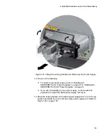
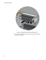
4. Use a #1 screwdriver to loosen the two screws that secure the plastic
cover over the terminal block and slide the cover to the right. You may
need to slightly lift the locking handle to access the bottom screw.
Refer to Figure 114
The plastic cover might not be present if you used the right angle
terminals to connect the lead wires to the terminal block. If this is the
case, skip this step.
Figure 114. Opening the Plastic Window over the Terminal Block
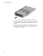
5. Use a #3 screwdriver to remove the negative (-) lead wire from the
terminal block. The negative lead wire is on the right. Refer to Figure
115 on page 183.
Summary of Contents for AT-FAN08
Page 10: ...Figures 10...
Page 12: ...Tables 12...
Page 16: ...Preface 16...
Page 38: ...Chapter 1 Overview 38...
Page 60: ...Chapter 2 Virtual Chassis Stacking 60...
Page 82: ...Chapter 4 Installing the Chassis 82 Figure 34 Example of Adjusting the Equipment Rack Brackets...
Page 104: ...Chapter 4 Installing the Chassis 104...
Page 140: ...Chapter 5 Powering On the Chassis 140...
Page 166: ...Chapter 7 Cabling the AT XEM2 Line Card Ports 166...


