Chapter 5: Powering On the Chassis
118
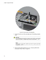
5. Secure the wire with the nut and washer removed in step 2, and an 8
mm wrench, as shown in Figure 73.
Allied Telesis recommends tightening the nut and washer to 26 inch-
lbs.
Figure 73. Securing the Bare Grounding Wire to the Grounding Post
6. After connecting the grounding wire, go to “Choosing a Method for
Summary of Contents for AT-FAN08
Page 10: ...Figures 10...
Page 12: ...Tables 12...
Page 16: ...Preface 16...
Page 38: ...Chapter 1 Overview 38...
Page 60: ...Chapter 2 Virtual Chassis Stacking 60...
Page 82: ...Chapter 4 Installing the Chassis 82 Figure 34 Example of Adjusting the Equipment Rack Brackets...
Page 104: ...Chapter 4 Installing the Chassis 104...
Page 140: ...Chapter 5 Powering On the Chassis 140...
Page 166: ...Chapter 7 Cabling the AT XEM2 Line Card Ports 166...


