background image

AT-AR256E v3 4 Ports ADSL2/2+ Router User Manual 

55 

To disable a remote log: 

1.


Select the IP address to be deleted from the 

Select a logging destination 

drop-down menu. 

2.


To temporarily implement the changes, click 

Apply

3.


To make changes permanent, click 

Save Settings

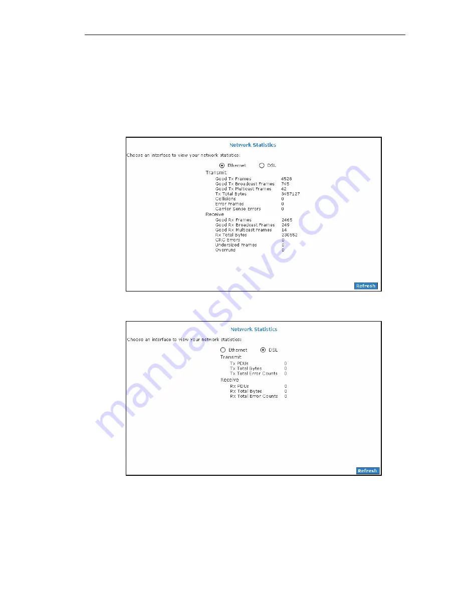
Network Statistics 

The Ethernet and DSL statuses are displayed in this page. To view the Network Statistics, go to the 

Status 

menu


then click 

Network Statistics


Figure 48: Network Statistics – Ethernet 


Figure 49: Network Statistics – DSL 

Summary of Contents for AT-AR256E v3

Page 1: ...PN 613 000984 Rev A AT AR256E v3 4 Ports ADSL2 2 Router User Manual ...

Page 2: ...ct names company names logos or other designations mentioned herein are trademarks or registered trademarks of their respective owners Allied Telesis Inc reserves the right to make changes in specifications and other information contained in this document without prior written notice The information provided herein is subject to change without notice In no event shall Allied Telesis Inc be liable ...

Page 3: ... BE LIABLE FOR DAMAGES OR LOSS INCLUDING BUT NOT LIMITED TO DIRECT INDIRECT SPECIAL WILFUL PUNITIVE INCIDENTAL EXEMPLARY OR CONSEQUENTIAL DAMAGES DAMAGES FOR LOSS OF BUSINESS PROFITS OR DAMAGES FOR LOSS OF BUSINESS OF ANY CUSTOMER OR ANY THIRD PARTY ARISING OUT OF THE USE OR THE INABILITY TO USE THE PRODUCT OR THE SOFTWARES INCLUDING BUT NOT LIMITED TO THOSE RESULTING FROM DEFECTS IN THE PRODUCT O...

Page 4: ...te measures Important Appendix A contains translated safety statements for installing this equipment When you see the go to Appendix A for the translated safety statement in your language Wichtig Anhang A enthält übersetzte Sicherheitshinweise für die Installation dieses Geräts Wenn Sie sehen schlagen Sie in Anhang A den übersetzten Sicherheitshinweis in Ihrer Sprache nach Vigtigt Tillæg A indehol...

Page 5: ... Package Contents 11 Device Design 11 Back Panel 11 Front Panel 12 Chapter 2 About the Web User Interface 13 Accessing the Web User Interface 13 Web User Interface Components 13 Buttons 13 Menus 14 Chapter 3 Basic Menu 15 Home 15 Quick Start 15 LAN Configuration 16 Diagnostics 17 Chapter 4 Advanced Menu 18 WAN 18 New Connection 18 ADSL Modulation 22 Connection Scan 23 LAN 24 LAN Configuration 24 L...

Page 6: ...47 Routing Table 48 System Password 48 Changing the System Password 48 Changing the Timeout Settings 49 Firmware Upgrade 49 Restoring the Default Settings 49 Chapter 5 Security Menu 50 IP Filters 50 LAN Isolation 51 Chapter 6 Status Menu 52 Connection Status 53 System Log 53 Remote Log 54 Network Statistics 55 DHCP Clients 56 QoS Status 56 Modem Status 57 Product Information 57 Chapter 7 Help Menu...

Page 7: ...n Scan 23 Figure 15 LAN Configuration 24 Figure 16 LAN Group Configuration 25 Figure 17 LAN Clients 27 Figure 18 UPnP 28 Figure 19 SNTP 28 Figure 20 IGMP Proxy 29 Figure 21 Enable WAN Access Update 30 Figure 22 DNS Proxy 31 Figure 23 Dynamic DNS Client 32 Figure 24 Port Forwarding 32 Figure 25 Bridge Filters 34 Figure 26 Web Access Control 35 Figure 27 Egress 37 Figure 28 Layer 2 Egress 37 Figure ...

Page 8: ...0 Figure 42 IP Filters 50 Figure 43 LAN Isolation 51 Figure 44 Status menu 52 Figure 45 Connection Status 53 Figure 46 System Log 53 Figure 47 Remote Log Settings 54 Figure 48 Network Statistics Ethernet 55 Figure 49 Network Statistics DSL 55 Figure 50 DHCP Clients 56 Figure 51 QoS Status 56 Figure 52 Modem Status 57 Figure 53 Product Information 57 Figure 54 Help menu 58 ...

Page 9: ...e router Chapter 2 About the Web User Interface introduces the web user interface general settings how to select options and how to move among menus Chapters 3 7 Explain the usage of the various menus Document Conventions This guide uses several conventions that you should become familiar with before you begin to install the product Note A note provides additional information Please go to the Alli...

Page 10: ...oducts Products for return or repair must first be assigned a return materials authorization RMA number A product sent to Allied Telesis without an RMA number will be returned to the sender at the sender s expense To obtain an RMA number contact Allied Telesis Technical Support through our web site http www alliedtelesis com support Sales or Corporate Information You can contact Allied Telesis for...

Page 11: ...owing minimum requirements Software Operating System Any operating system can be used Browser Internet Explorer 6 0 7 0 Netscape Navigator 3 02 Hardware 233MHz processor CD ROM Drive Ethernet network adapter Package Contents Package contents include Router Telephone cable Ethernet cable Power adaptor Documentation CD Quick Setup Guide Device Design Back Panel The back panel provides ports to power...

Page 12: ...panel Label Action Description POWER Off No power is supplied to the device Steady light Connected to a AC power supply ETHERNET Off No Ethernet connection Steady light Connected to an Ethernet port Blinking light Transmitting Receiving data DSL Blinking light Establishing DSL signal Steady light DSL signal is established INTERNET Off No Internet connection Steady light Connected to the Internet B...

Page 13: ... is 192 168 1 1 3 When authentication is enabled default the Log In page will appear On the Log In page enter the Username and Password The default Username is manager and Password is friend 4 Click Log In Web User Interface Components Buttons commands and menus make up the browser based user interface Buttons Apply Click to implement the configuration changes Clicking Apply will not implement the...

Page 14: ... Basic menu provides the Home Quick Start LAN Configuration and Diagnostics links Advanced Menu The Advanced menu provides advanced configuration settings for existing connections At least one WAN connection must be configured before implementing advanced WAN configuration features At least one LAN group must be defined before implementing advanced LAN configuration features Security Menu Security...

Page 15: ...tion Information page gives you an idea about the status of your Internet connection This page includes a Connect Disconnect button When clicked the router makes an attempt to connect to the Internet using the parameters saved in the router Router Information This page provides all the necessary information to determine the firmware version and Ethernet MAC Address Local Network The Local Network ...

Page 16: ...3 4 Ports ADSL2 2 Router User Manual LAN Configuration LAN Configuration displays the current IP address assigned to the router When you want to access the router use the stated IP Address Figure 5 LAN Configuration ...

Page 17: ...he router is properly connected to the WAN This test may take a few seconds to complete To perform the test select your connection from the list then press the Test button Before running this test make sure you have a valid DSL connection Figure 6 DSL Modem Test To run Modem Test 1 Select the Basic menu then click Diagnostics This opens the Full Modem Test page 2 Click Test The test results will a...

Page 18: ... new connections If you have multiple virtual connections you may need to utilize the static routing capabilities of the modem to pass data correctly WAN connections types include PPPoE Connection PPPoA Connection Static Connection DHCP Connection Bridge Connection PPPoE Connection PPP or Point to Point Protocol is a method of establishing a network connection session between network hosts PPPoE i...

Page 19: ...connection PPP or Point to Point Protocol is a method of establishing a network connection session between network hosts It usually provides a mechanism for authenticating users Logical Link Control LLC and Virtual Circuit VC are two different methods of encapsulating the PPP packet Contact your service provider to determine which encapsulation is being used on your Internet connection Figure 9 Ne...

Page 20: ...r DNS addresses can be identified These servers resolve the name of the computer to the IP address mapped to it and thus enable you to access other web servers by typing the symbolic name host name Figure 10 New Static Connection Setup DHCP Connection Dynamic Host Configuration Protocol allows the router to automatically obtain a IP address from the server This option is commonly used when the IP ...

Page 21: ...re bridged connection does not assign any IP address to the WAN interface NAT and firewall rules are not enabled This connection method makes the router act as a bridge for passing packets between the WAN interface and the LAN interface Figure 12 New Bridge Connection Setup ...

Page 22: ...Modulation ADSL Modulation allows you to select any combination of DSL training modes Leave the default values if you are unsure or the service provider did not provide this information In most cases this page should not be modified Figure 13 ADSL Modulation ...

Page 23: ... by the service provider Before the router can begin scanning the connection the telephone line has to be plugged into the router Figure 14 Connection Scan To perform connections scan 1 Select the Basic menu 2 Select Automatic 3 Click Next 4 Select the appropriate settings and proceed with the login information 5 Click Connect ...

Page 24: ...DHCP enabled the DHCP configuration must reside within the same subnet The default gateway is the routing device used to forward all traffic that is not addressed to a station within the local subnet Your ISP will provide you with the default gateway Address Figure 15 LAN Configuration To configure the LAN groupings 1 Select the Advanced menu 2 Select LAN LAN Configuration 3 Select ETHERNET in LAN...

Page 25: ...an IP address automatically Netmask The subnet mask of your router Enables disables PPP unnumbered feature PPP IP Address IP Address The IP address should be different but within the same subnet as the WAN side IP address This field enables you to change the IP address of the router IP Address The default IP address of the router as shown is 192 168 1 1 Netmask The default subnet mask of your rout...

Page 26: ...e IP address of the router In other words if the IP address of the router is 192 168 1 1 default and you change the DHCP start end IP addresses to be 192 168 1 2 192 168 1 100 you cannot communicate with the router if your host has DHCP enabled Enable DHCP Server Lease Time The Lease Time is the amount of time that a network user is allowed to maintain a network connection to the router using the ...

Page 27: ... LAN Clients 1 Select Advanced menu 2 Select LAN LAN Clients This opens the LAN Clients page 3 Select a LAN Connection and enter IP Address Hostname and MAC Address 4 Click Apply 5 You can convert the dynamic into a static entry by clicking Reserve and then click Apply 6 To temporarily implement the settings click Apply 7 To make changes permanent click Save Settings Applications Applications incl...

Page 28: ...onments Figure 18 UPnP To enable UPnP check the enable UPNP checkbox then Apply Simple Network Time Protocol Simple Network Time Protocol SNTP is a protocol used to synchronize the system time to the public SNTP servers It uses the UDP protocol on port 123 to communicate between clients and servers Figure 19 SNTP To enable SNTP 1 Check Enable SNTP 2 Configure the following fields Primary SNTP Serv...

Page 29: ...net Group Management Protocol IGMP to report their multicast group memberships to neighboring routers Similarly multicast routers use IGMP to discover which of their hosts belong to multicast groups Your router supports IGMP proxy that handles IGMP messages When enabled your router acts as a proxy for a LAN host making requests to join and leave multicast groups or a multicast router sending multi...

Page 30: ...rface as the upstream interface Configure one or more LAN interface as the upstream interface To configure the IGMP Proxy 1 Select Advanced 2 Select Application IGMP Proxy 3 Configure the following interfaces Quickstart LAN group 1 4 Click Apply to temporarily apply the settings 5 To make changes permanent click Save Settings TR 068 WAN Access The TR 068 WAN Access page enables you to give tempora...

Page 31: ...ect the DNS Server Priority 1 Select Advanced 2 Select Application DNS Proxy 3 Select the DNS Server Priority Only Auto Discovered DNS Servers Only User Configured DNS Servers Auto Discovered then User Configured User Configured then Auto Discovered 4 Click Apply to temporarily apply settings 5 To make changes permanent click Save Settings Dynamic DNS Client Dynamic DNS allows the user to register...

Page 32: ... apply the settings 5 To make changes permanent click Save Settings Figure 23 Dynamic DNS Client Port Forwarding Port forwarding or virtual server allows you to direct incoming traffic to specific LAN hosts based on a protocol port number and protocol Using the Port Forwarding page you can provide local services for example web hosting for people on the Internet or play Internet games Port forward...

Page 33: ...ate new rules Enter Rule Name Protocol Port Start Port End and Port Map then click Apply 6 Continue to add rules as they apply from each category 7 Click Apply to temporarily activate the settings 8 To make changes permanent click Save Settings DMZ Settings Setting a host on your local network as demilitarized zone DMZ forwards any network traffic that is not redirected to another host via the Por...

Page 34: ...ilter rules are supported with bridge filtering Figure 25 Bridge Filters To configure Bridge Filters 1 Select Advanced 2 Select Application Bridge Filters This opens the Bridge Filters page 3 Select Enable Bridge Filters 4 To add a rule enter the source MAC address Destination MAC address and Protocol with desired filtering type then click Add You can also edit a rule that you created using the Ed...

Page 35: ...e Web Access 1 Select Advanced menu 2 Select Application Web Access Control 3 Select Enable 4 Select the connection used in Choose a connection 5 Configure the following fields Remote Host IP Remote Netmask Redirect Port 6 Click Apply to temporarily activate the settings on the page The WAN address is now added into the IP Access List This allows you to access your router remotely 7 To make change...

Page 36: ...oS4 CoS5 CoS6 The rules are 1 CoS1 has absolute priority and is used for Expedited Forwarding EF traffic This is always serviced till completion 2 CoS2 CoS5 is used for Assured Forwarding AF classes They are serviced in a strict round robin manner using the following priority scheme CoS2 CoS3 CoS4 CoS5 3 CoS6 is for Best Effort BE traffic This is only serviced when there is no other class of servi...

Page 37: ...mappings of the packets are untouched Figure 27 Egress Layer 2 Egress The Egress Layer 2 page allows you to map the CoS of an outgoing packet to user priority bits which is honored by the VLAN network Again this feature is only configurable on the WAN interface as VLAN is only supported on the WAN side in the current release Figure 28 Layer 2 Egress ...

Page 38: ...gress Egress Layer 3 enables you to map CoS to ToS so that the priority marking of outgoing packets can be carried over to the IP network Figure 29 Layer 3 Egress Field Description Interface Select the WAN interface to configure the QoS for outgoing packets LAN interface cannot be selected as VLAN is currently supported on the WAN side only Default Non IP Locally generated packets such as ARP pack...

Page 39: ...r Ingress modes Untrusted mode Layer 2 Layer 3 Static Untrusted Mode Untrusted is the default Ingress page setting for all interfaces In this mode no domain mapping is honored in the router All packets are treated as CoS6 best effort Figure 30 Untrusted mode Ingress ...

Page 40: ...ect Advanced menu 2 Select QoS Ingress 3 Select the quickstart interface 4 Select Layer 2 5 Select CoS1 in Class of Service and enter 5 in Priority Bits Any packet with priority marking 5 is mapped to CoS1 the highest priority that is normally given to voice packets 6 Click Apply to temporarily the settings 7 Select CoS2 in the Class of Service and 1 in Priority Bits Any packet that has a priority...

Page 41: ...ackets and ARP packets The default is CoS1 recommended To configure Ingress Layer 3 11 Select Advanced menu 12 Select QoS Ingress 13 Select the quickstart interface 14 Select Layer 3 15 Select CoS1 in Class of Service and enter 22 in Type of Service ToS Any incoming packet from LAN Group 1 layer 3 with a ToS of 22 is mapped to CoS1 the highest priority which is normally given to voice packets 16 L...

Page 42: ...nterface You are configuring QoS on this interface only Any WAN LAN interface that is not configured has the default Untrusted mode 6 Select CoS1 in Class of Service All incoming traffic from the ETHERNET interface receives CoS1 the highest priority 7 Click Apply to temporarily activate the settings 8 To make changes permanent click Save Settings QoS Shaper Configuration The QoS Shaper Configurati...

Page 43: ...e All CoSx traffic use a specific rate to which data will be shaped For example If CoS1 is configured to 100Kbits then even if 300Kbits of CoS1 data is being transmitted to the interface only 100Kbits will be sent out Low Latency Queue Discipline This is similar to the above algorithm except that CoS1 is not rate limited So in the example above CoS1 data is not rate limited to 100Kbits but instead...

Page 44: ...scipline Enabled In this second example Low Latency Queue Discipline is enabled CoS1 is not rate controlled hence the field is disabled CoS2 takes 100Kbits when there is no CoS1 packet CoS6 has 300Kbits when there is no CoS1 or CoS2 packets This is similar to the HTB queue discipline as they are both rate based algorithm except that CoS1 is handled differently Figure 36 Low Latency Queue Disciplin...

Page 45: ...acket CoS2 CoS3 CoS4 each has 10 and CoS6 has 70 This is similarly to the Low Latency Queue discipline except that one is packet based and the other is rate based Figure 37 PRIOWRR enabled Policy Routing Configuration The Policy Routing Configuration enables you to configure policy routing and QoS Figure 38 Policy Routing Configuration ...

Page 46: ...P ICMP Specify and none If you choose Specify you need to enter the protocol number in the box next to the Protocol field This field cannot be configured alone additional fields like IP Source MAC and or Ingress Interface should be configured This field is also required if the source port or destination port has been entered Source Port The source protocol port You cannot configure this field with...

Page 47: ...ferent IP domain users to access the Internet through the router Figure 39 Static Routing The New Destination IP is the address of the remote LAN or host to which you want to assign a static route Enter the IP address of the host for which you wish to create a static route here For a standard Class C IP domain the network address is the first three fields of the New Destination IP while the last f...

Page 48: ... System Password in the LAN Configuration page Changing the System Password To change the System Password 1 Click the Advanced menu 2 Click System Password This opens the System Password page 3 Select Enable Authentication 4 Enter your password 5 Re enter your password in the Confirm Password text box 6 To temporarily implement the settings click Apply 7 To make changes permanent click Save Settin...

Page 49: ...the router will reboot You will need to log back into the router after the firmware upgrade is completed To update the firmware 1 Click the Advanced menu then click Firmware Upgrade This opens the Firmware Upgrade page 2 Click Browse then locate the firmware file 3 Click Update Gateway The update may take a few minutes Make sure that the power is not turned off during the update process Restoring ...

Page 50: ... the LAN device In this page you can block specific traffic for example block web access or any traffic from a host on your local network A database of predefined IP filters allows you to apply one or more filtering rules to one or more members of a defined LAN group You can view the rules associated with a predefined filter and add the available rules for a given category You can also create edit...

Page 51: ...ategory Select User then click New 5 The Rule Management page opens for you to create new rules Enter Rule Name Protocol Port Start Port End and Port Map then click Apply The rules you create will appear in the Available Rules pane in the User category You can view or delete the rules you create 6 Continue to add rules as they apply from each category using the Add button 7 To temporarily implemen...

Page 52: ...s information about monitoring the router status and viewing product information Your router allows you to view the following status and product information Connection Status System Log Remote Log Network Statistics DHCP Clients QoS Status Modem Status Product Information Figure 44 Status menu ...

Page 53: ...nternet connection To view the Connection Status go to the Status menu then click Connection Status Figure 45 Connection Status System Log System Log displays the router log Depending on the severity level the information log will generate log reports to a remote host if remote logging is enabled To view the System Log go to the Status menu then click System Log Figure 46 System Log ...

Page 54: ...er condition that causes the router to stop functioning Alert Conditions that require immediate correction such as a corrupted system database Critical Critical conditions such as hard drive errors Error Error conditions that generally have less serious consequences than errors in the emergency alert and critical levels Warning Conditions that warrant monitoring Notice Default Conditions that are ...

Page 55: ...tion drop down menu 2 To temporarily implement the changes click Apply 3 To make changes permanent click Save Settings Network Statistics The Ethernet and DSL statuses are displayed in this page To view the Network Statistics go to the Status menu then click Network Statistics Figure 48 Network Statistics Ethernet Figure 49 Network Statistics DSL ...

Page 56: ...ess IP Address Host Name and Lease Time To view the DHCP Clients go to the Status menu then click DHCP Clients Figure 50 DHCP Clients QoS Status This page displays the Quality of Service and the packet statistics To view the QoS Status go to the Status menu then click QoS Status Figure 51 QoS Status ...

Page 57: ...tus To view the Modem Status go to the Status menu then click Modem Status Figure 52 Modem Status Product Information This page displays the product information and software versions To view the Product Information go to the Status menu then click Product Information Figure 53 Product Information ...

Page 58: ... provides documentation for various topics like Firewall Bridge Filters LAN Clients LAN Group Configuration PPP Configuration IP QoS and Routing Information Protocol To access Help click the Help menu Figure 54 Help menu In order to obtain help on a topic click on the relevant command ...

Reviews: