background image

Quick Install Guide

5

C613-04043-01 REV D

5.

Place the switch in its operating location

If installing the switch in a rack:

Remove the rubber feet

Attach the rack-mounting brackets.

Use the screws provided with the switch to mount it in a rack. Other screws 
may damage the switch.

Mount the switch in the rack

6.

Apply AC power to the switch

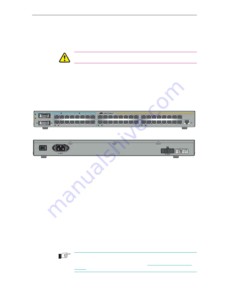
Plug the power cord into the AC power connector on the switch’s rear 
panel, as shown in Figure 1. The FAULT LED may light for one or two 
seconds as the switch runs internal tests. If the LED remains lit, refer to the


AT-8800 Series Hardware Reference

 for troubleshooting information.

Figure 1: AT-8848 front panel and rear panel with AC power inlet.

7.

Fit the power cord retaining clip.

A retaining clip is supplied with the switch for the AC power inlet on the 
switch’s rear panel. Fit this clip to secure the power cord in place.

8.

Check that the Power LED on the switch’s front panel lights green

If the PWR LED fails to light, refer to the

 AT-8800 Series Hardware Reference


for troubleshooting information.

9.

Connect the Redundant Power Supply (Optional) 

AT-8800 Series switches have a Redundant Power Supply (RPS) connector 
on their rear panel.

The Switch is designed to operate with the AT-RPS8000 RPS, which can be 
purchased separately. See the 

AT-8800 Series Hardware Reference

 or contact 

your authorised Allied Telesis distributer or reseller for more information.

10. Install GBICs (Optional)


Slide the GBICs into the GBIC slots. Press each GBIC firmly into place. 

A range of GBICs have been tested and approved for use with AT-8800 Series switches. 
See the AT-8800 Series Hardware Reference or contact your authorised Allied Telesis 
distributor or reseller for more information, or visit www.alliedtelesis.com/support/
software.

49

50

49

50

LINK

ACT

L /A

L /A

GBIC

ENABLED

FAULT

GBIC

GBIC

D/C

L /A

LINK 100M

ACT

LINK 10M

ACT

L /A

FULL DUP

HALF DUP

COL

PORT ACTIVITY

AT-8848

Intelligent Workgroup Switch

RESET

ASYN0

FAULT

PWR

RPS

33 

 35 

 37 

 39 

 41 

 43 

 45 

 47

34 

 36 

 38 

 40 

 42 

 44 

 46 

 48

1  

3  

5  

7   

9  

11  

13  

15 

2   

4   

6   

8   

10  

12  

14  

16

17  

19  

21  

23  

25   

27   

29  

31

18  

20  

22  

24  

26   

28   

30  

32

D/C

L /A

L /A

D/C

L /A

L /A

D/C

L /A

Summary of Contents for AT-8800 Series

Page 1: ...AT 8800 Series Switch Quick Install Guide AT 8824 AT 8848 ...

Page 2: ...hanges in specifications and other information contained in this document without prior written notice The information provided herein is subject to change without notice In no event shall Allied Telesis be liable for any incidental special indirect or consequential damages whatsoever including but not limited to lost profits arising out of or related to this manual or the information contained he...

Page 3: ...One serial cable for connecting the switch to a terminal or PC One 19 inch rack mount kit One AT 8800 Series Quick Install Guide One Safety and Statutory Information booklet One AT 8800 Series Documentation and Tools CD ROM which includes the complete AT 8800 Series Document Set and utilities One warranty card AT 8800 Series Printed Acrobat PDF Website Documentation Roadmap AT 8800 Series Safety a...

Page 4: ...without exceeding maximum cable length limitations See the AT 8800 Series Hardware Reference for cable length specifications Installing the Switch This equipment must be earthed Follow these steps to install the switch 1 Read the safety information For safety information see the Safety and Statutory Information booklet A copy of this booklet is supplied with each switch and can also be found on th...

Page 5: ...t refer to the AT 8800 Series Hardware Reference for troubleshooting information 9 Connect the Redundant Power Supply Optional AT 8800 Series switches have a Redundant Power Supply RPS connector on their rear panel The Switch is designed to operate with the AT RPS8000 RPS which can be purchased separately See the AT 8800 Series Hardware Reference or contact your authorised Allied Telesis distribut...

Page 6: ...2 Set the communication parameters Set the communication parameters on your terminal or terminal emulation program to Baud rate 9600 Data bits 8 Parity None Stop bits 1 Flow control Hardware 3 Check the power supply Ensure that the On Off switch is in the On position and that the switch is receiving power PWR LED lights green 4 Log in After the switch has booted the log in prompt appears If the lo...

Page 7: ...nce 1 Select a PC to browse to the switch from You can browse to the switch from any PC that is running a supported operating system with a supported browser installed JavaScript must be enabled If you are using a toolbar or plug in on your browser to block pop ups disable it while using the GUI The GUI displays detailed configuration options and information in pop up windows You need to know the ...

Page 8: ... ROM bundled with each switch contains the complete Documentation Set for AT 8800 Series switches and their expansion options as well as tools for managing the switch This includes The AT 8800 Series Statutory and Safety Information booklet which provides safety and statutory information for the switch and its expansion options The AT 8800 Series Hardware Reference which provides detailed informat...

Reviews: