Quick Install Guide
5
C613-04026-01 REVD
2.
Choose a suitable site for the router
A flat, clean, dust free surface.
3.
Unpack the router
Verify the package contents. If any items are damaged or missing, contact
your sales representative.
4.
Place the router in its operating location
See the previous Selecting a Site section for guidelines on choosing a
suitable location.
Do not stack AR300 Series routers directly on top of one another as this will
impede air flow past the fan vents.
5.
Check the supply voltage and the router’s rated voltage
AR300 Series routers are fitted with a universal mains power supply that
will function over the range 100-240 VAC and 50–60Hz.
The specific power supply requirements for a particular model are displayed on
the rear or underside of the router. If the supply is outside the accepted range for
the router, the router may not operate, and damage to the router may result.
6.
Apply power to the router
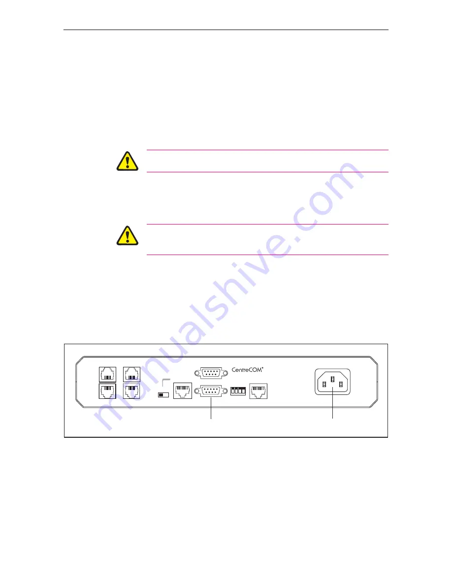
Plug the power cord into the AC power connector on the router’s rear
panel (Figure 1). The Power LED on the router’s front panel will light, and
the System LED (also on the front panel) will light briefly.
If the power LED fails to light, or the System LED lights continuously, refer
to the troubleshooting section later in this guide.
Figure 1: Power inlet and console port locations on the rear panel of an AR300 Series router.
7.
Connect the data cables
Make sure that each cable connection is secure.
8.
Initiate router start-up
Using the terminal cable supplied with your router, connect a VT100-
compatible terminal, or the COM port of a PC running a terminal
emulation program such as Windows Terminal, to the console port (port 0)
on the router’s rear panel.
300REAR
AR310
ETHERNET 0
CONFIG
MDX
HUB
VOICE 2
VOICE 1
VOICE 3
VOICE 0
PC
4
3
2
1
BRI 0
PORT 1 (RS232)
PORT 0 (RS232)
100•240 VAC, 50•60Hz, 300mA.
DISCONNECT MAINS SUPPLY BEFORE REMOVING
LID•NO USER SERVICEABLE PARTS
Power inlet
Console port


