Allied Systems SDN Installation Maintenance And Service Manual Download Page 11

B

45-015, REV. 9/21

3.14 Operator’s Controls 

Some lift trucks are equipped with a single lever to 
control both hoist and tilt functions, others have separate 
levers for each function. Refer to your lift truck manual 
for more information. 

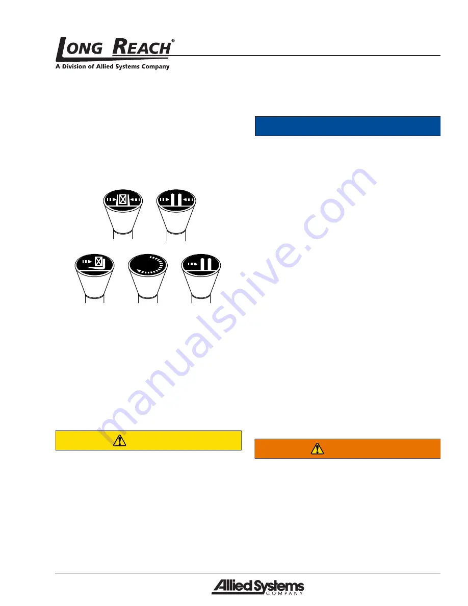
For clarity, the direction of arm movement is shown on 
the control handle. To move the arms in the direction 
shown, pull the handle towards the operator. To move 
the arms in the opposite direction, the push the handle 
away from the operator. (Figure 3-5)

Clamp

Fork position

Push/pull

Rotate

Sideshift

Figure 3-5  Operator controls

Lifting speed is controlled by the speed of the engine 
and the position of the control lever. Engine speed has 
no effect on lowering speed.

Before going on the job, shift the truck control levers 
one way and then the other to determine which direc-
tion the attachment moves when the levers are shifted. 
Make sure the attachment moves smoothly throughout 
its travel, without binding or pinching hoses. 

CAUTION

Equipment damage hazard.

Injury or equipment damage may result 
if the attachment does NOT operate 
smoothly.

Do not take malfunctioning equipment on 
the job. Check with your supervisor about 
needed repairs.

3.15 Industry Standards

ANSI/ITSDF B56.1-2016 is the published sequence and 
direction standard for lever- and hand-type controls. 

Notice

The chart on the following page shows 
industry standards. Your equipment 
may be different. If you do not routinely 
operate this equipment, refresher 
training is recommended. You must 
reacquaint yourself with this manual and 
the equipment before starting, and then 
proceed slowly.

Special controls such as automatic devices should be 
identified, preferably according to the recommendations 
in Figure 3-6.

When a function is controlled by a pair of push buttons, 
they should operate in the same sense as the lever 
controls. For example, pushing a button located to the 
rear (relative to the operator’s position) should serve 
the same function as moving a control lever to the rear.

3.16 Clamp Open Control

Effective October 7, 2010, safety standard ANSI/ITSDF 
B56.1, Section 7.25.7 covers all lift trucks with a load 
bearing clamp (paper roll clamp, carton clamp, etc.), 
and requires the driver to make two distinct motions 
before opening or releasing the clamp. For example, 
you must press a switch and then move a lever to 
unclamp the load. This requirement applies to new 
and used attachments being mounted on trucks which 
shipped from the factory after October 7, 2010, and is a 
recommended feature to be installed on dealer orders 
and existing applications.

WARNING

Load loss hazard.

Injury or equipment/load damage may 
result if a fork positioner attachment is 
used to clamp a load. The fork positioner 
does not have enough clamping force to 
safely hold a load.

Always support the load with the forks. 
Do not use fork positioning attachments 
as clamps. 

Summary of Contents for SDN

Page 1: ...B 45 015 REV 9 21 Installation Maintenance and Service Manual SDN SJN SLJ SLN AND SPN Heavy Duty Sideshifters...

Page 2: ...Hydraulic Hazards 9 3 10 Electrical Hazards 9 3 11 Maintenance Warnings 9 3 12 Load Handling 10 3 13 Load Positioning 10 3 14 Operator s Controls 11 3 15 Industry Standards 11 3 16 Clamp Open Control...

Page 3: ...ate the Long Reach nameplate upper left corner on the body Record the information from the nameplate along with the date received at the bottom of this page If the nameplate is missing look for the se...

Page 4: ...Dual Side Shifter with Base Frame CAPACITY 24 load center 055 5 500 lb 065 6 500 lb 100 10 000 lb 150 15 000 lb 175 17 500 lb OUT TO OUT 083 83 0 091 91 0 098 98 0 MODEL SPECIFIC DESIGNATOR MOUNTING C...

Page 5: ...51 0 520 52 0 720 72 0 800 80 0 MODEL SPECIFIC DESIGNATOR MOUNTING CLASS A ITA Class II B ITA Class III C ITA Class IV F ITA Class V G ITA IV Class Stretched BR1 Standard Long Reach load backrest dri...

Page 6: ...060 6 000 lb 100 10 000 lb 155 15 500 lb 185 18 500 lb 300 30 000 lb 360 36 000 lb OVERALL WIDTH 59 59 0 74 74 0 078 78 0 300 30 0 335 33 5 420 42 0 450 45 0 480 48 0 500 50 0 540 54 0 600 60 0 620 6...

Page 7: ...r death WARNING Indicates a hazardous situation which if not avoided could result in death or serious injury Carefully read the message that follows to prevent serious injury or death CAUTION Indicate...

Page 8: ...partment Always operate an attachment from the operator s seat never while standing next to the lift truck Do not allow riders on the truck at any time Always use reverse when carrying a load that imp...

Page 9: ...skills and information proper tools and equipment Work in a method that is safe correct and meets your company s requirements Do not attempt to make adjustments or perform maintenance or service unle...

Page 10: ...overhead clear ances Watch in all directions Avoid sudden stops Before disconnecting hydraulic lines be sure to lower all loads and relieve all hydraulic pressure The load could fall on you or escapi...

Page 11: ...the following page shows industry standards Your equipment may be different If you do not routinely operate this equipment refresher training is recommended You must reacquaint yourself with this manu...

Page 12: ...t Rearward or up Forward or down Slope Clockwise Counterclockwise Rearward or up Forward or down Fork position Together Apart Rearward or up Forward or down Trip Engage Release Rearward or up Forward...

Page 13: ...an conforms to ANSI recommendations and the notches are not damaged 3 Thetruckhydraulicsystemmustsupplytotheattach ment hydraulic oil that meets the specifications required to operate the attachment p...

Page 14: ...the button clicks into place WARNING Equipment failure hazard The attachment could fall off the truck if the quick hook is not properly installed Slide plate must click into place If the slide plate...

Page 15: ...ast in the vertical position run the attach menttothelimitofalloperations Afterthisprocedure check that the truck s hydraulic reservoir oil level is at the recommended level 8 Beforeplacingtheattachme...

Page 16: ...r blocksof wood can be place under the body of the attachment to raise the rear 6 Toreinstall followtheinstallationprocedureinSection 4 2 of this manual Notice Equipment damage hazard Equipment damage...

Page 17: ...ts per chart 6 2 Torque Specifications The following torque values are to be used on all fasteners unless otherwise specified Lubricated refers to fasteners in the As Received condition which is norma...

Reviews: