background image

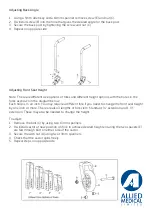
Adjusting Wheel Locks

1.  Loosen the two screws (A) with a 5mm Allen key
2.  The wheel lock clamps (C) can now be moved along the frame to the desired position so 

that the wheel lock engages at least 1/8 inch into the tire and locks properly to prevent the 
chair moving when engaged

3.  Always retighten wheel lock hardware by alternating between the screws by tightening 

a little at a time. This prevents over-clamping on one set of hardware which can lead to 
binding of the fasteners and increased difficulty in removal

4.  Repeat steps on opposite side

Note: For a low profile scissor lock, use a 5mm Allen key to loosen the two bolts. For the other 
three wheel locks, loosen the hardware using a 4mm Allen key and a 10mm spanner

Summary of Contents for Ki Mobility Catalyst 5

Page 1: ...equired measurements for set up Letter Body Part Required Y N A Hip B Thigh Right B Thigh Left C Right Leg C Left Leg D Right back height below scapula D Left back height below scapula E Shoulder to seat F Top of head to seat G Right elbow to seat G Left elbow to seat H Back width below scapula Two 10mm Spanner 13mm Spanner 17mm Spanner 19mm Spanner 24mm Spanner Phillips Screwdriver Wheelchair Scr...

Page 2: ...emove the latch catch assembly using a 4mm Allen key and 10mm spanner refer to the bottom right bolt in the picture on the right 2 Remove bolt assembly H using 4mm Allen key and 10mm spanner 3 Reconnect to the latch assembly and set at desired depth determined by the holes available in the frame see diagram and table below 4 Move the frame insert in or out so the latch assembly is in the correct p...

Page 3: ...m Allen key and a 10mm spanner 4 Repeat steps on opposite side Adjusting Seat to Footplate Height on an Extension Tube Hanger Short medium and long tubes are available see table below for height ranges 1 Remove the nut holding the extension tube in place using a 8mm spanner 2 Slide the extension tube up or down the hanger the appropriate height and line up the holes in the hanger with the extensio...

Page 4: ...Repeat steps on opposite side if required Adjusting Height Adjustable Back Post 1 Remove back upholstery or back support and attachment hardware if required 2 Remove the sleeve C bolt washer D and nut E using a 4mm Allen key and 10mm spanner 3 Select appropriate height utilising the available holes on the back post see diagram below for height ranges 4 Re install the sleeve bolt washer and nut in ...

Page 5: ...as shown in the diagram below Each hole is an inch You may require a different fork if you need to change the front seat height by one inch or more There are also 3 lengths of fork stem Standard extension and 1 extension These may also be needed to change the height To adjust 1 Remove the bolt C by using two 13mm spanners 2 Re install castor at new position on fork to achieve desired height ensuri...

Page 6: ...ber is achieved with the lowest located washers that are between the axle plate and the frame See diagram below for different camber angles that can be achieved Adjusting Centre of Gravity 1 Remove rear wheels from quick release axle 2 Loosen nut on outside of axle using a 24mm spanner until you are able to move the axle receiver forward or back along to the next groove on the inside of the axle p...

Page 7: ...ving when engaged 3 Always retighten wheel lock hardware by alternating between the screws by tightening a little at a time This prevents over clamping on one set of hardware which can lead to binding of the fasteners and increased difficulty in removal 4 Repeat steps on opposite side Note For a low profile scissor lock use a 5mm Allen key to loosen the two bolts For the other three wheel locks lo...

Page 8: ... of the axle with a 24mm spanner then turn the threaded axle sleeve in or out to desired width 2 Re tighten the nut 3 Repeat on opposite side Note Check that there is sufficient clearance so that the wheel does not rub on the side guards arm supports or wheel locks Adjusting T Arm Height 1 Install T Arm assembly into the receiver Ensure the latch B clicks into place 2 Adjust the height by loosenin...

Page 9: ...sen 4 Locate the adjustment screw on the top of the top of the castor housing Using the 5mm Allen key turn the screw clockwise to move the castors forward away from the rear wheel Turn the screw anti clockwise to move the castors rearward towards the rear wheel 5 Keep turning the screw in the direction necessary to re square the castors 6 Use a square against the front of the castor barrel check f...

Page 10: ...t or back depending on toe in or out that hold the axle plate on One washer will go on with the camber washers and the other will go on the bolt above it Putting an extra set of washers in will change the measurement by around 8mm If for example you have 516mm at the front and 500mm at the rear and your wheel centre height is 305mm Take the wheels off and loosen all the bolts holding the axle plat...

Page 11: ...Width Seat Depth Seat to foot plate length angle depth Back height and angle COG shoulder position and access to rear wheel Seat height shoulder position and access to rear wheel Seat rake for optimal pelvic positioning Wheel locks at optimal tension for client Wheel base width optimal position for access to rear wheel Positioning belt if applicable Arm rest height if applicable Check push handle ...

Reviews: