506762-01
Page 21 of 24
Issue 1143
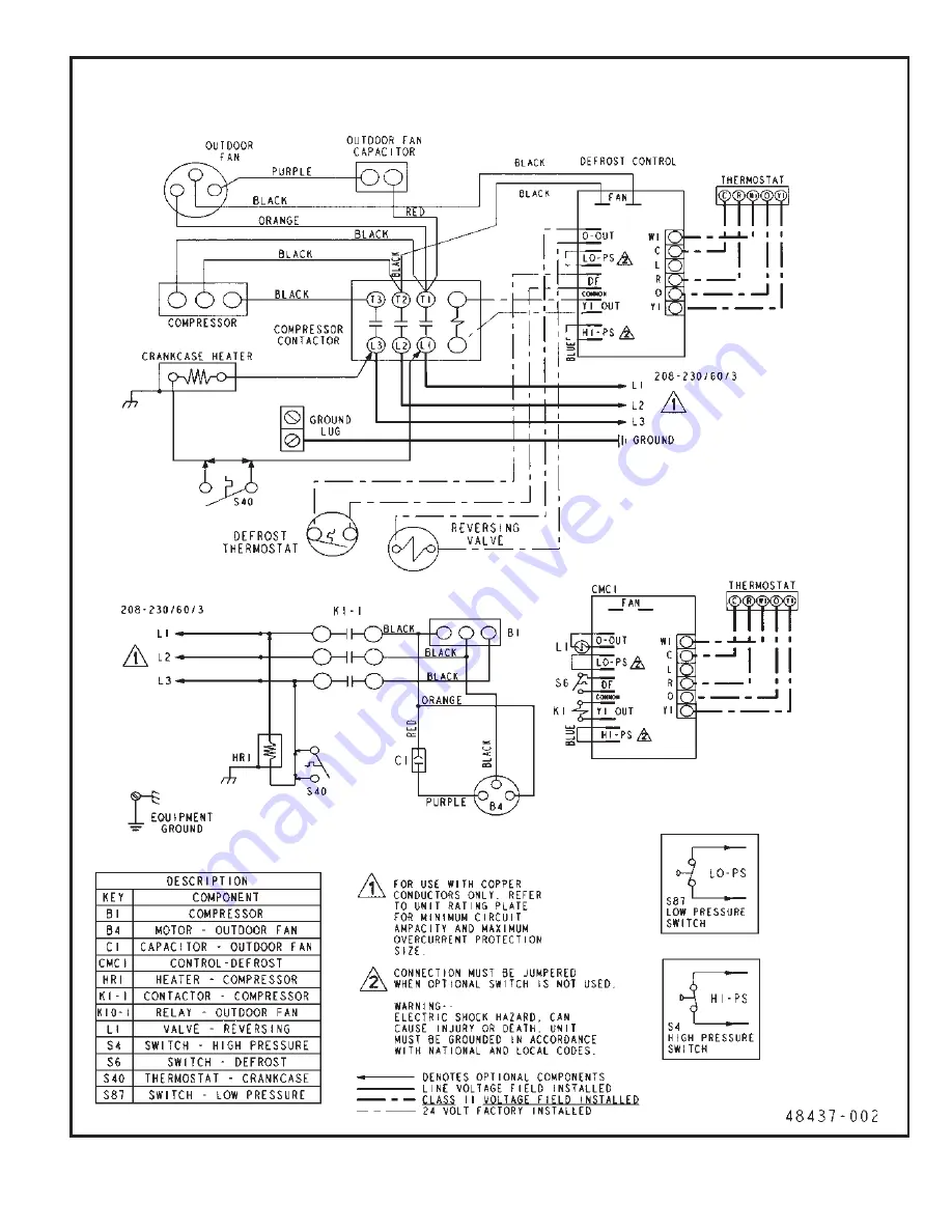
Wiring Diagram for 3 Phase, 230 V Models
Page 1: ...ipment Installation and service performed by unqualified persons can result in property damage personal injury or death WARNING Sharp metal edges can cause injury When installing the unit use care to...
Page 2: ...t will transmit sound or vibration to the living area or adjacent buildings Install the unit high enough above the ground or roof to allow adequate drainage of defrost water and prevent ice buildup In...
Page 3: ...ower coil installation instructions for additional wiring application diagrams and refer to unit rating plate for minimum circuit ampacity and maximum overcurrent protection size 1 Install line voltag...
Page 4: ...ces for line sets over 50 Thermostat Designations Some connections may not apply Refer to specific thermostat and indoor unit Without Auxiliary Heat With Auxiliary Heat Do not connect C common connect...
Page 5: ...are some points to consider when placing and installing a high efficiency outdoor unit Placement Be aware that some localities are adopting sound ordinances based on how noisy the unit is at the neigh...
Page 6: ...e Caulk PVC Pipe Fiberglass Insulation Outside Wall IMPORTANT Refrigerant lines must not contact structure NOTE Similar installation practices should be used if line set is to be installed on exterior...
Page 7: ...The tube end must stay bottomed in the fitting during final assembly to ensure proper seating sealing and rigidity 7 Install the fixed orifice or thermal expansion valve which is sold separately and...
Page 8: ...he proper fixed orifice size for each unit In nonstandard applications the fixed orifice provided with the indoor unit may not be Flushing Procedure IMPORTANT The line set and or indoor coil must be f...
Page 9: ...e of 30 vacuum to 250 psi with dampened speed to 500 psi Gauge hoses must be rated for use at up to 800 psi of pressure with a 4000 psi burst rating Liquid and SuctionLine Service Valves The liquid li...
Page 10: ...ions and indoor unit must be checked for leaks Using an Electronic Leak Detector 1 Connect the high pressure hose of the manifold gauge set to the suction valve service port Normally the high pressure...
Page 11: ...the nitrogen cylinder and remove the manifold gauge hose from the cylinder Open the manifold gauge valves to release the nitrogen from the line set and indoor unit 8 Reconnect the manifold gauge to th...
Page 12: ...If not do not start equipment until the power company has been consulted and the voltage condition corrected 6 Set thermostat for cooling demand turn on power to indoor blower and close the outdoor u...
Page 13: ...pair any leaks then use the weigh in method to charge the unit 1 Recover the refrigerant from the unit 2 Conduct a leak check then evacuate as previously outlined 3 Weigh in the charge according to th...
Page 14: ...6 2 7 1 2 6 5 5 7 1 3 6 5 8 7 1 4 6 6 1 8 1 5 6 3 4 8 1 6 6 7 7 8 1 7 6 9 0 9 1 8 6 1 4 9 1 9 6 3 7 9 1 0 7 6 0 0 2 1 7 9 3 0 2 2 7 2 7 0 2 3 7 6 0 1 2 p m e T F e r u s s e r P g i s P 4 7 0 4 1 2 5...
Page 15: ...ermostats When the room thermostat is placed in the emergency heat position the outdoor unit control circuit is isolated from power and the field supplied relays bypass the outdoor thermostats An ambe...
Page 16: ...ent accumulated compressor run time period during one thermostat run cycle This time period must occur before a defrost cycle is initiated The defrost interval can be adjusted to 30 T1 60 T2 or 90 T3...
Page 17: ...from operating at its most efficient level Turn all electric power to unit OFF at disconnect switch es before performing any maintenance operations on system Unit may have multiple power supplies Elec...
Page 18: ...outdoor coil may require frequent cleaning depending on environmental conditions Clean the outdoor coil with an unpressurized water hose to remove surface contaminants and debris It may be necessary t...
Page 19: ..._______ Installer _________________________________ City ___________________ State ______________ Unit Model No ______________ Serial No ___________________ Service Technician ________________________...
Page 20: ...Page 20 of 24 506762 01 Issue 1143...
Page 21: ...506762 01 Page 21 of 24 Issue 1143 Wiring Diagram for 3 Phase 230 V Models...
Page 22: ...Page 22 of 24 506762 01 Issue 1143 Wiring Diagram for 3 Phase 460V Models...
Page 23: ...er is unable to provide warranty service check online at www alliedair com 3 Be prepared to furnish the following information a complete model and serial number b proof of required periodic maintenanc...
Page 24: ...3 Modification change or alteration of the unit except as expressly directed in writing by Allied Air 4 Improper use accident neglect or unreasonable use or operation of the unit including operation o...