92
F238006
Section 5 Service Procedures
To reduce the risk of electrical shock, fire, explosion, serious injury or death:
• Disconnect electrical power to the washer-extractor before servicing it.
• Close the gas shut-off valve to the washer-extractor (when applicable) before servicing it.
• Never start the washer-extractor with any guards/panels removed.
• Whenever ground wires are removed during servicing, these ground wires must be
reconnected to ensure that the washer-extractor is properly grounded.
W461R1
WARNING
© Copyright, Alliance Laundry Systems LLC – DO NOT COPY or TRANSMIT
k. Mark the shaft where it contacts the bearing
sleeve. This mark will be used to determine if
the procedure described below unseats the
bearing.
l. Drive the shaft through the bearings by
impacting the end of the shaft with a rubber
hammer. If this force is insufficient, a
sledgehammer can be used if care is taken to
protect the end of the shaft. If the force from a
rubber hammer or sledgehammer is
insufficient, use a puller to drive the shaft
through the bearings. A distinctive "pop" will
be heard once the bearings become unseated
from the shaft.
m. Verify that the shaft is loose from the bearings
by moving the basket forward. The shaft should
move freely though the bearing.
n. Remove the screws and the brass collar from
the basket.
o. Remove the basket from the machine.
p. Remove the nylon retainer and carbon seal
from the shell.
NOTE: If necessary, pull the shell back away from
the frame by removing the 6 nuts holding the
stiffener plate and shell to the frame.
q. Clean the shell (inside and out), removing all
dirt, oil and dried silicone.
Mounting Instructions
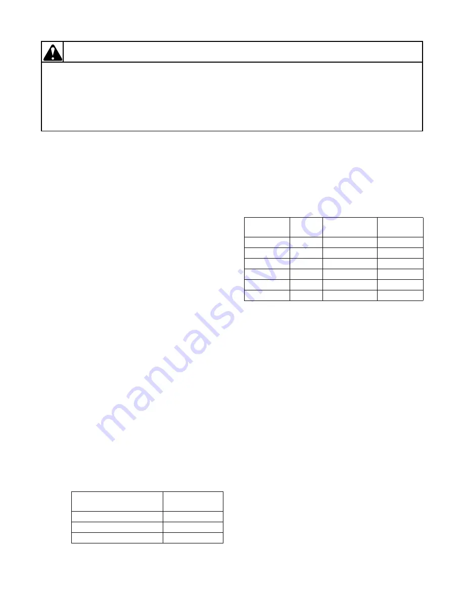
a. Using a micrometer, verify that shaft diameter
is within the +0.000/-0.004 inches in tolerance.
Refer to Table 1. Measure the location on the
shaft where the bearings will be mounted.
Check the end of the shaft for any burrs or lips
created from impact damage. If the shaft is not
within the listed tolerance, it should be
replaced.
b. Clean and lubricate the entire shaft and apply
oil between the bearing inner race and the shaft.
c. Remove the plastic inserts from the bearing(s).
d. Slide the bearing(s) over the shaft to verify that
the shaft is the correct size and that the bearings
have not been damaged in shipment.
e. Torque the front bearing to the frame. Refer to
Table 2 for specifications.
f. Bolt the rear bearing to the frame. Leave the
bolts loose enough so that the rear bearing can
be moved against the frame.
NOTE: Do not put silicone in the seal area.
g. On all models except for UW35, install a gasket
between the stiffener plate and the shell back
and align the bolts. Refer to Figure 30.
NOTE: File the shell opening if the new cartridge
does not fit without interference.
NOTE: Remove any burrs from the key that is
located on the end of the basket shaft.
h. Install a new cartridge seal onto the machine
(without using RTV) with the gasket against
shell back, leaving the bolts loose, refer to
Figure 30.
NOTE: Make sure that the shell is tightened to the
frame and the stiffener plate.
i. Clean the alignment shaft and apply a light coat
of oil to it with a clean cloth to assist with the
insertion of it through the bearings.
Model
Shaft
Diameter
+/- Tolerance
(inches)
35, 60
2.4375
2.4375-2.4335
80, 100
2.9375
2.9357-2.9335
125
3.4375
3.4375-3.4335
Table 1
Model UW Bearing Bolt size
Torque (ft.-
lbs. (N-M)
35
Front
5/8-18 x 2-3/4 197 (267)
35
Rear
9/16-18 x 2-1/2 140 (190)
60
Front
5/8-18 x 2-3/4 197 (267)
60
Rear
9/16-18 x 2-1/2 140 (190)
80,100
All
3/4-16 x 2-3/4 285 (386)
125
All
7/8-14 x 3
500 (678)
Table 2


