background image

1.6

INTRODUCTION

Thank you for purchasing an 

Allen 

machine.  The following pages are designed to help you

gain safe and efficient service from your machine.

IMPORTANT:

This ‘Owners Handbook’ should be regarded as part of the mower as it gives

essential information regarding mower safety, operation, maintenance and specifications. Read
and understand this handbook prior to operating your machine for the first time.  Make sure you
are familiar with all the controls and points of regular maintenance. If you have any doubts,
consult your local authorised dealer who will be pleased to give you assistance.

IMPORTANT: 

This machine is designed solely for cutting grass and other low lying ground

vegetation within the limitations stated in this manual. Use in any other way is considered as
contrary to the intended use. Compliance with and strict adherence to the conditions of opera-
tion, service and repair as specified in this handbook also constitute essential elements of the
intended use.
This machine should be operated, serviced and repaired only by persons who are familiar with
its particular characteristics and who are acquainted with the relevant safety procedures.

The safety precautions listed in this handbook and all other generally recognised regulations on
safety must be observed at all times.
Any arbitrary modifications carried out to this machine may relieve the manufacturer of 
liability for any resulting damage or injury.

Allen

machines are robustly constructed and designed for efficient economical 

performance under normal mowing conditions.  Correct operation and maintenance will ensure
a long and satisfactory service life.  Prior to despatch from our factory every effort is made to
ensure that your mower is delivered in perfect condition.

Throughout this handbook all references to 

left

and 

right

are as viewed from behind the han-

dlebar, in the direction of forward travel.  

This handbook is based on information available at the time of publication.

We reserve the right to amend product specifications without prior notification.

111-1519 (A)  28/1/08  4:44 pm  Page 1.6

Summary of Contents for Hovertrim 184E XR44

Page 1: ... English Version PART NUMBER 111 1519 A ISSUE 28 01 08 Hovertrim OWNER S HANDBOOK MODELS 184E XR44 Hovertrim 185E XR16 Hovertrim Manufactured by Hayter Limited ...

Page 2: ......

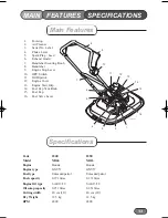
Page 3: ...71 litres Engine Oil type SAE 13 30 SAE 13 30 Oil sump capacity 0 251 litres 0 251 litres Cutting width 40 cm 16 40 cm 16 Dry Weight 12 5 kg 12 5 kg RPM 4800 4800 1 Footstop 2 Air Cleaner 3 Serial No Label 4 Choke Lever 5 Spark Plug Lead 6 Exhaust Guard 7 Handlebar Securing Knob 8 Handlebar 9 Engine Stop Lever 10 OPC Switch 11 Oil Dipstick 12 Engine Cover 13 Engine Start Grip 14 Fuel Cap Vent Knob...

Page 4: ......

Page 5: ...3 Fuel Type 1 14 1 19 Operating The Mower 1 14 Controls 1 14 1 15 Starting 1 15 Cutting Grass 1 15 Stopping 1 16 Adjusting the Cutting Height 1 16 Flexiblade Replacement 1 16 Before Mowing 1 17 1 21 Mower Maintenance 1 17 Engine 1 17 Carburettor Adjustments 1 18 Air Cleaner Service 1 18 Spark Plug Service 1 19 Keeping Engine Clean 1 19 Deck Housing 1 19 Securing Nuts and Bolts 1 19 1 20 Oil Servic...

Page 6: ...dbook also constitute essential elements of the intended use This machine should be operated serviced and repaired only by persons who are familiar with its particular characteristics and who are acquainted with the relevant safety procedures The safety precautions listed in this handbook and all other generally recognised regulations on safety must be observed at all times Any arbitrary modificat...

Page 7: ...ing parts This warranty does not apply to any unit that has been tampered with altered misused abused or used for hire and will become invalid if non genuine parts are fitted This warranty does not cover for minor mechanical adjustments unless they are due to defective material or workmanship Consult the Owner s Handbook or an Authorised Service Dealer for assistance when making these adjustments ...

Page 8: ...for accidents or hazards occurring to other people or their property While using the machine always wear substantial footwear and long trousers Do not operate the equipment when barefoot or wearing san dals Thoroughly inspect the area where the machine is to be used and remove all objects which may be thrown by the machine WARNING Petrol is highly flammable Store fuel in containers specifically de...

Page 9: ... refuelling Always pull the starter cord slowly until resistance is felt Then pull the cord rapidly to avoid kickback and prevent hand or arm injury Operate only in daylight or good artificial light Avoid using the machine on wet grass where feasible Always be sure of your footing on slopes Walk never run Operate across the face of slopes never up and down Exercise extreme caution when changing di...

Page 10: ...machine Before refuelling Keep all nuts bolts and screws tight to ensure that the equipment is in safe operating condition Frequently check fuel lines and fittings for cracks or leaks and replace if necessary Never check for a spark when the spark plug is removed Use approved tester Inspect the exhaust periodically and replace if worn or leaking Never crank the engine with the spark plug removed N...

Page 11: ...intenance Storage Safety Symbols Safety Alert Be aware to the possibility of injury Danger of severing toes or fingers in cutting mechanism Carefully read the Owners Handbook before using the machine Danger of being hit by thrown objects Stop engine and remove spark plug lead before working on the mower Keep bystanders at a safe distance from the mower Engine Stop STOP Information Symbols Hearing ...

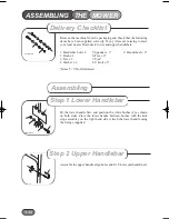
Page 12: ... U Bolt x 2 Items 5 9 Not Illustrated Fit the lower handle first and position the white bushes 2 as shown on both sides Place the lower handle between bushes with the kick stop assembley on the right hand side Attach the lower handle using the fixings supplied Assemble the upper handle align holes and fit U bolts and hand wheel HAY G00117 A 8 9 DTP 000 003 A 1 2 2 3 4 4 1 12 ASSEMBLING THE MOWER 1...

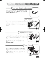
Page 13: ...e oil filler cap and wipe the dipstick with a clean cloth Insert the dipstick into the oil filler neck but do not screw it in then remove to check the oil level The oil level is correct when it is at the full mark on the dipstick DO NOT OVERFILL Always use clean fresh unleaded petrol Purchase fuel in quantities that can be used within 30 days Never mix oil with petrol Fill to base of neck to allow...

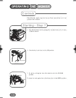
Page 14: ...or 3 turns counterclockwise 2 Turn the fuel valve lever to the ON position 3 To start a cold engine move the choke lever to the CLOSED position To restart a warm engine leave the choke lever in the OPEN position N E P O FUEL CAP VENT OPEN Starting Step 1 1 14 Controls OPERATING THE MOWER HAY G00122 A FUEL VALVE LEVER ON HAY G00123 A CLOSED CHOKE LEVER OPEN ...

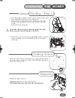
Page 15: ... to prevent damage to the starter 6 If the choke lever was moved to the CLOSED position to start the engine gradually move it to the OPEN position as the engine warms up Start at the outside border of the lawn and go round working towards the centre Always control the mower with both hands keeping the mower flat on the ground Release the engine stop lever Emergency stop Release the engine stop lev...

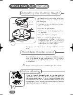
Page 16: ... of 200mm and fit as above Drain the fuel by running the engine until the fuel tank is empty and the engine stops Remove the spark plug lead and allow the engine to cool Turn the mower on its left hand side and ensure that the carburet tor is uppermost Wearing protective gloves remove flexiblade and replace with new To prevent accidents thoroughly inspect the area and remove all objects which when...

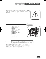
Page 17: ...ler Cap Dipstick 5 Finger Guard 6 Start Grip 7 Fuel Cap Vent Knob 8 Fuel Cap 9 Choke Lever 10 Air Cleaner 11 Carburettor Should only be made by an authorised Honda dealer Under no circumstances should the engine be adjusted to run at a speed in excess of that shown on the Declaration of Conformity HAY G00144 A 1 2 3 4 5 6 7 8 9 10 11 Engine Carburettor Adjustments MOWER 1 17 MAINTENANCE ...

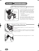
Page 18: ...over Insert the tabs on the bottom of the cover into the slots in the bottom of the base Tilt the cover upwards until the two catches 2 hold it in place Use only an approved spark tester 1 to check for a spark as shown in the diagram Replace the spark plug every 100 hours or every season whichever occurs first A spark plug wrench is available from any authorised Honda service dealer Check the spar...

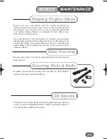
Page 19: ...al cool ing fins and surfaces may require cleaning to prevent overheating and engine damage We recommend that this service be carried out by an authorised dealer Remove grass debris from the top and underside of the deck immedi ately after use Regularly check that all securing nuts and bolts are tight Replace missing or damaged items immediately Check the oil level daily before starting the engine...

Page 20: ...tor parts To ensure your mower is maintained in good working order it is important that the following procedure is adopted Refer to the engine handbook as necessary Drain fuel from the engine by operating the engine until it stops Disconnect the spark plug lead turn off fuel valve lever Change the engine oil Remove the engine spark plug and pour 15ml of engine oil into the engine cylinder and repl...

Page 21: ...ions transposed into national law Also Directive 2004 108 EC Electromagnetic Compatibility and regulations Complies with harmonized standards EN 14910 EN 55012 BS EN 61000 4 2 EN61000 4 3 EN 50366 NOISE INFORMATION The noise levels measured in accordance with European Standard EN 14910 Machine sound power level Sound level at operator s ear Declaration done and technical documentation kept at HAYT...

Page 22: ... Open fuel tap if fitted Engine will not start Engine under load Raise height of cut Fuel starvation Fill fuel tank Engine cold Set throttle to choke position Incorrect contaminated fuel Drain fuel tank and fill with correct fuel Spark plug lead disconnected Connect spark plug lead Throttle setting incorrect Set throttle to start position Faulty spark plug Clean and adjust gap or replace Engine ru...

Page 23: ...olt Bent crankshaft Consult your dealer Damaged impeller or cutter disc Consult your dealer Uneven cut Flexiblade out of balance Replace flexiblade Engine running slow Consult your dealer Impeller air vents blocked Check and unblock Poor hovering Underdeck not clean Clean Cutter disc loose Tighten bolts TROUBLE SHOOTING 1 23 ...

Page 24: ...81 1 21 ENGINE MTG SCREW M6X20 SFS 111 1500 4 22 SCREW M5 45 PPD 111 1501 8 23 NYLOC NUT M5 FLANGED 111 1502 8 24 5X5X20 SQUARE ENDED DRIVE KEY 111 1503 1 25 BOLT UNF 2 1 4 X 1 4 HEX HEAD 111 1504 1 26 SPRING DISC 40mmOD 1 4 ID 111 1515 1 27 M6 U BOLT BZP H292026 2 28 BAIL ARM H290239 1 29 SWITCH BOX RH 111 1525 1 30 UPPER HANDLE H290237 1 31 RETURN SPRING 111 1773 1 32 P CLIP 15 8 4 6 NATURAL 111...

Page 25: ...1 25 1 2 4 6 9 10 11 13 14 15 16 17 18 19 20 21 22 23 24 25 26 27 28 29 30 31 32 33 34 35 38 40 41 12 4 7 27 39 37 3 36 36 37 8 MAINFRAME PARTS LIST ...

Page 26: ...1 26 NOTES ...

Page 27: ...1 27 Serial No Engine Type GXV57 Engine Honda Engine Type GXV57 Engine Honda Date of Sale Your Local Dealer CUSTOMER INFORMATION ...

Page 28: ...nufactured by Hayter Limited Hayter Limited Spellbrook Bishop s Stortford Herts CM23 4BU England Tel 44 0 1279 723444 Fax 44 0 1279 600338 e mail sales hayter co uk www hayter co uk YOUR HAYTER DEALER IS ...

Reviews: