


2
Rockwell Automation Publication 440R-IN081B-EN-P - February 2020
Back EMF Monitoring Relay Module
Excessive Heat Prevention
For most applications, normal convective cooling keeps the relay within
the specified operating range. Verify that the specified temperature
range is maintained. Usually, proper spacing of components within an
enclosure is sufficient for heat dissipation.
Additional provisions are necessary to cool equipment when high
ambient temperatures are encountered. Do not bring in unfiltered
outside air. Place the MSR55P standstill module in an enclosure to help
protect it from a corrosive atmosphere. Harmful contaminants or dirt
could damage components or cause improper operation. In extreme
cases, air conditioning helps protect against heat buildup within the
enclosure.
Wiring Requirements and Recommendation
• Allow for at least 50 mm (2 in.) between I/O wire ducts or
terminal strips and the relay.
• Route incoming power to the relay by a path separate from the
device wiring. Where paths must cross, their intersection must
be perpendicular.
• Do not run signal or communications wiring and power wiring
in the same conduit. Route wires with different signal
characteristics by separate paths.
• Separate wiring by signal type. Bundle wiring with similar
electrical characteristics together.
• Separate input wiring from output wiring.
• Label wiring to all devices in the system. Use tape, shrink-
tubing, or other more dependable means to label wire. Use
colored insulation as well to identify wiring by signal
characteristics. For example, use blue for DC wiring and red for
AC wiring.
Enclosure Requirements
Install the MSR55P standstill module in an enclosure that meets the
environmental requirements of Pollution Degree 2, where only
non-conductive pollution occurs except that occasionally a temporary
conductivity caused by condensation is to be expected.
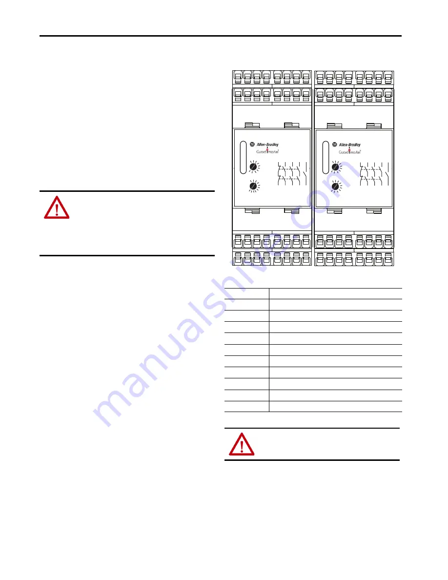
Relay Face and Terminal Identification
Table 1 - Terminal Assignments and Functions
ATTENTION:
Before you install and wire any device, disconnect
power to the system.
Calculate the maximum possible current in each power and
common wire. Observe all electrical codes that dictate the
maximum current allowable for each wire size. Current above the
maximum rating causes wiring to overheat, which can cause
damage.
Terminal
Function
A1(+)…A2(-)
Power supply
L1/L2/L3
Motor connections
11/12
Voltage-free redundant monitoring (non-safety) contacts (N.C.)
23/24, 33/34, 43/44
Voltage-free redundant safety contacts (N.O.)
53/54
Voltage-free monitoring (auxiliary) contact (N.O.)
X1/X2
Connection for feedback circuit
X3/X2
Reset for fault conditions.
A3(+)…A4(-)
Power supply for semiconductor outputs
ON
Non-safety semiconductor output indicates that safety outputs are ON.
ERR
Non-safety semiconductor output indicates fault condition.
ATTENTION:
The outputs 53…54, ON and ERR are only
monitoring outputs and must not be used in safety circuits.
53 54 L1 L2 L3
X1 X2 X3 11 23 33 43
12 24 34 44
A3 A4 ON ERR A1 A2
OUT
ERR
PWR
53 54 L1 L2 L3
X1 X2 X3 11 23 33 43
12 24 34 44
A3 A4 ON ERR A1 A2
OUT
ERR
PWR
.2
.4
.7
MSR55P
1
1.5
2
3
4
.5
.3
.2
.4
.7
ts
Vm
1
1.5
2
6
.5
.3
2
4
7
MSR55P
10
15
0
3
0
2
40
5
3
.2
.5
1
ts
x10mVm
1.5
2
4
.7
.3
6
3
3
3
5
3
4
1
1
3
2
3
3
4
5
4
4
2
1
4
2
4
3
3
5
3
4
1
1
3
2
3
3
4
5
4
4
2
1
4
2
4
3
4 3