Allen-Bradley FLEX I/O 1794-IC16 Installation Instructions Manual Download Page 10

10

    FLEX I/O 48V DC Digital Input and Output Modules  

Publication 1794-IN105C-EN-P - July 2018

Input 4

A-4

C-39

B-21

Output 4

A-4

B-21

Input 5

A-5

C-40

B-22

Output 5

A-5

B-22

Input 6

A-6

C-41

B-23

Output 6

A-6

B-23

Input 7

A-7

C-42

B-24

Output 7

A-7

B-24

Input 8

A-8

C-43

B-25

Output 8

A-8

B-25

Input 9

A-9

C-44

B-26

Output 9

A-9

B-26

Input 10

A-10

C-45

B-27

Output 10

A-10

B-27

Input 11

A-11

C-46

B-28

Output 11

A-11

B-28

Input 12

A-12

C-47

B-29

Output 12

A-12

B-29

Input 13

A-13

C-48

B-30

Output 13

A-13

B-30

Input 14

A-14

C-49

B-31

Output 14

A-14

B-31

Input 15

A-15

C-50

B-32

Output 15

A-15

B-32

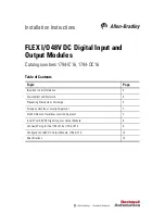
A = Input/Output terminals


B = Common terminals


C = Power terminals (C-34 to C-51 on 1794-TB3 and 1794-TB3S; C-34 and C-51 on 1794-TB2)

(1)

3-wire devices use input, supply and common. 2-wire devices use input and supply.

Wiring Connections for 1794-IC16 and 1794-OC16

1794-IC16

1794-OC16

1794-TB3, 1794-TB3S

1794-TB2, 1794-TB3, 
1794-TB3S

Input

Input 
Terminal

48V DC 
Supply

Common

(1)

Output

Output 
Terminal

Common

Summary of Contents for FLEX I/O 1794-IC16

Page 1: ...portant User Information 2 Environment and Enclosure 3 Preventing Electrostatic Discharge 3 European Hazardous Location Approval 5 North American Hazardous Location Approval 7 Install Your 48V DC Digital Input or Output Module 8 Connect Wiring for the 1794 IC16 or 1794 OC16 9 Configure Your 48V DC Output Module 1794 OC16 14 Specifications 14 ...

Page 2: ...grams in this manual are included solely for illustrative purposes Because of the many variables and requirements associated with any particular installation Rockwell Automation Inc cannot assume responsibility or liability for actual use based on the examples and diagrams No patent liability is assumed by Rockwell Automation Inc with respect to use of information circuits equipment or software de...

Page 3: ...ith a flame spread rating of 5VA or be approved for the application if nonmetallic The interior of the enclosure must be accessible only by the use of a tool Subsequent sections of this publication may contain more information regarding specific enclosure type ratings that are required to comply with certain product safety certifications In addition to this publication see the following Industrial...

Page 4: ...uipment may be impaired ATTENTION If this equipment is used in a manner not specified by the manufacturer the protection provided by the equipment may be impaired ATTENTION Read this document and the documents listed in the Additional Resources section about installation configuration and operation of this equipment before you install configure operate or maintain this product Users are required t...

Page 5: ... The following applies to products marked II 3 G Are Equipment Group II Equipment Category 3 and comply with the Essential Health and Safety Requirements relating to the design and construction of such equipment given in Annex II to EU Directive 2014 34 EU See the EU Declaration of Conformity at http www rockwellautomation com global certification overview page for details The type of protection i...

Page 6: ...64 1 when applied in Zone 2 environments The enclosure must be accessible only by the use of a tool This equipment shall be used within its specified ratings defined by Rockwell Automation The instructions in the user manual shall be observed This equipment must be used only with ATEX certified Rockwell Automation backplanes Earthing is accomplished through mounting of modules on rail Devices shal...

Page 7: ...empérature pour les environnements dangereux Lorsque plusieurs produits sont combinés dans un système le code de température le plus défavorable code de température le plus faible peut être utilisé pour déterminer le code de température global du système Les combinaisons d équipements dans le système sont sujettes à inspection par les autorités locales qualifiées au moment de l installation WARNIN...

Page 8: ...base adapter You cannot install the module unless the connector is fully extended 3 Make sure the pins on the bottom of the module are straight so they will align properly with the connector in the terminal base 4 Position the module 7 with its alignment bar 6 aligned with the groove 5 on the terminal base 5 Press firmly and evenly to seat the module in the terminal base unit The module is seated ...

Page 9: ... are internally connected together 4 1794 IC16 only Connect the associated input common 3 wire devices only to the corresponding terminal on the 16 33 row B for each input as indicated in the Wiring Connections for 1794 IC16 and 1794 OC16 table Commons are internally connected together 5 Connect V DC power to terminal 34 on the 34 51 row C 6 Connect V DC common to terminal 16 on the 16 33 row B 7 ...

Page 10: ...B 28 Output 11 A 11 B 28 Input 12 A 12 C 47 B 29 Output 12 A 12 B 29 Input 13 A 13 C 48 B 30 Output 13 A 13 B 30 Input 14 A 14 C 49 B 31 Output 14 A 14 B 31 Input 15 A 15 C 50 B 32 Output 15 A 15 B 32 A Input Output terminals B Common terminals C Power terminals C 34 to C 51 on 1794 TB3 and 1794 TB3S C 34 and C 51 on 1794 TB2 1 3 wire devices use input supply and common 2 wire devices use input an...

Page 11: ... 2 3 4 5 6 7 8 9 10 11 12 13 14 15 16 35 36 37 38 39 40 41 42 43 44 45 46 47 48 49 50 51 34 Inputs Outputs Commons 1794 TB3 shown V COM V Voltage A B C V COM Connect V DC power to terminal C 34 Connect V DC common to terminal B 16 Use B 33 and C 51 for daisychaining to the next terminal base unit V Note Terminals C 35 C 50 are not present on the 1794 TB2 A B C 0 15 16 33 34 51 Sink Input Common V ...

Page 12: ...Time for 1794 IC16 table Image Table Memory Map for the 1794 IC16 Module Dec 15 14 13 12 11 10 9 8 7 6 5 4 3 2 1 0 Oct 17 16 15 14 13 12 11 10 7 6 5 4 3 2 1 0 Read I15 I14 I13 I12 I11 I10 I9 I8 I7 I6 I5 I4 I3 I2 I1 I0 Write Not used set to 0 Input Filter FT1 12 15 Input Filter FT0 0 11 Where I Input status FT0 Input filter time for inputs 0 11 FT1 Input filter time for inputs 12 15 ATTENTION This ...

Page 13: ...ts Description 02 01 00 Filter Time for inputs 00 11 Selected Filter Time Actual Filter Time 05 04 03 Filter Time for inputs 12 15 0 0 0 Filter Time 0 Default 256 μs 1256 μs 0 0 1 Filter Time 1 512 μs 1512 μs 0 1 0 Filter Time 2 1 ms 2 ms 0 1 1 Filter Time 3 2 ms 3 ms 1 0 1 Filter Time 4 4 ms 5 ms 1 0 1 Filter Time 5 8 ms 9 ms 1 1 0 Filter Time 6 16 ms 17 ms 1 1 1 Filter Time 7 32 ms 33 ms 1 0 0 7...

Page 14: ...t the end of its life this equipment should be collected separately from any unsorted municipal waste Specifications 48V DC Input Module 1794 IC16 Attribute Value Number of inputs 16 nonisolated sinking Recommended terminal base unit 1794 TB3 1794 TB3S 1794 TB3K 1794 TB3SK On state voltage min 30V DC On state voltage nom 48V DC On state voltage max 60V DC On state current min 2 0 mA 30V DC On stat...

Page 15: ...nition by the module Specifications 48V DC Output Module 1794 OC16 Attribute Value Number of outputs 16 nonisolated sourcing Recommended terminal base unit 1794 TB3 1794 TB3S 1794 TB3K 1794 TB3SK Output voltage min 30V DC Output voltage nom 48V DC Output voltage max 60V DC 45 C 55V DC 55 C Output current rating 8 0 A 16 outputs 0 5 A On state current min 2 0 mA per channel On state current max 500...

Page 16: ...mm 3 7 x 3 7 x 2 7 in Weight approx 82 g 2 89 oz 110 g 3 88 oz Indicators field side indication 16 yellow status indicators customer device driven 16 yellow status indicators logic driven External DC power supply voltage nom 48V DC External DC power voltage range 30 60V DC includes 5 AC ripple External DC power supply current range 51 mA 30V DC 82 mA 48V DC 107 mA 60V DC 13 27 mA North American te...

Page 17: ... 5 95 non condensing Vibration IEC60068 2 6 Test Fc Operating 5 g 10 500 Hz Shock operating IEC60068 2 27 Test Ea Unpackaged shock 30 g Shock nonoperating IEC60068 2 27 Test Ea Unpackaged shock 50 g Emissions CISPR 11 Group 1 Class A with appropriate enclosure ESD immunity IEC 61000 4 2 6 kV contact discharges 8 kV air discharges Radiated RF immunity IEC 61000 4 3 10V m with 1 kHz sine wave 80 AM ...

Page 18: ... 2014 30 EU EMC Directive compliant with EN 61131 2 Programmable Controllers Clause 11 EN 61000 6 2 Industrial Immunity EN 61000 6 4 Industrial Emissions EN 61131 2 Programmable Controllers Clause 8 Zone A B European Union 2011 65 EU RoHS compliant with EN 50581 Technical documentation Ex European Union 2014 34 EU ATEX Directive compliant with EN 60079 0 General Requirements EN 60079 15 Potentiall...

Page 19: ...esents the safe operating range for the module under various conditions of user supplied 48V DC supply voltages and ambient temperatures Normal mounting safe operating range includes Other mounting positions including inverted horizontal safe operating range 41 29 50 55 60 Normal Mounting Horizontal Other Mounting including Vertical and Inverted Horizontal Mounting Voltage max Temperature max Norm...

Page 20: ...be returned follow these procedures Documentation Feedback Your comments will help us serve your documentation needs better If you have any suggestions on how to improve this document complete this form publication RA DU002 available at http www rockwellautomation com literature Rockwell Automation maintains current product environmental information on its website at http www rockwellautomation co...

Reviews: