background image

21

7.

Accessoires

Désignation

Réf.

Connexion transversale – 2,5 N/2 noir 

1492-CJLJ5-2-BL

Connexion transversale – 2,5 N/2 rouge

1492-CJLJ5-2-R

Connexion transversale – 2,5 N/2 bleu

1492-CJLJ5-2-B

Connexion transversale – 2,5 N/2 jaune

1492-CJLJ5-2

Marker

Réf.

1492-M6X10

Power Supply

24 V DC Output 

15 W

1606-XLP15E

30 W

1606-XLP30E

50 W

1606-XLP50E

100 W

1606-XLP100E

120 W (5 A)

1606-XLE120E

DIR 10000043404

(Version 00)

Summary of Contents for 931S-B1C6D-DC

Page 1: ...Installation Instructions 1 Beipackinformation 8 Notice d utilisation 15 de en fr DIR 10000043404 Version 00 Bridge Converter 3 Way 931S B1C6D DC 10000043404 ...

Page 2: ......

Page 3: ...icient distance or insulation between adjacent devices Appropriate safety measures against electrostatic discharge ESD should be taken during assembly and adjustment work on the 931S B1C6D DC 2 Application The 3 Way Bridge Converters 931S B1C6D DC are used for galvanic isolation and conversion of voltage signals Input and output signals can be calibrated switched via DIP switches It is not necessa...

Page 4: ...connect the plugs Disengage the top part of the housing by carefully pressing the latches on both sides 1 Pull out the top part of the housing and the electronics section until they unlock 2 3 3 Settings Set input and output ranges minimum input values and measuring span via the DIP switches SW1 according to the following table 1 1 2 Offset Excitation Voltage SW1 3 ...

Page 5: ...V 20 mV 1 0 0 1 50 mV 50 mV 1 0 1 0 100 mV 100 mV 1 0 1 1 200 mV 200 mV 1 1 0 0 500 mV 500 mV 1 1 0 1 Output 0 10 V 0 0 0 5 V 0 1 0 20 mA 1 0 4 20 mA 1 1 Supply voltage to the bridge 10 V 1 0 0 5 V 1 0 1 4 8 10 2 V adjustable 0 1 0 4 8 10 2 V adjustable 0 1 1 and offset is also adjustable Response Standard output signals 0 Inverse output signals 1 0 open 1 closed ...

Page 6: ...4 F R1 DMS R2 R4 R3 U 10 11 12 7 8 9 1 2 3 4 5 6 Power supply Power PLC 0 5V Power supply Measuring bridge Bridge Bridge 3 4 Application ...

Page 7: ...city of cross connection ⱕ 2 A Terminal assignments 1 Supply voltage to the bridge 2 Supply voltage to the bridge 3 Not assigned 4 Input 5 Input 6 Not assigned 7 Output 0 4 20 mA 8 Output 0 5 10 V 9 Output 0 V reference potential 10 Power supply 24 Vdc cross connected 11 Power supply GND cross connected 12 Not assigned Wire cross section max 2 5 mm2 Multi wire conncection max 1 mm2 two wires with ...

Page 8: ...6 92 4 90 111 4 73 4 38 GND 24 Vdc 17 5 Cross connections for multiple devices 6 Dimensions in mm ...

Page 9: ...Jumper 2 pole red 1492 CJLJ5 2 R Plug In Jumper 2 pole blue 1492 CJLJ5 2 B Plug In Jumper 2 pole yellow 1492 CJLJ5 2 Marker Cat No 1492 M6X10 Power Supply 24 V DC Output 15 W 1606 XLP15E 30 W 1606 XLP30E 50 W 1606 XLP50E 100 W 1606 XLP100E 120 W 5 A 1606 XLE120E DIR 10000043404 Version 00 ...

Page 10: ...llation und Auswahl der Zuleitungen müssen beachtet werden Bei Anwendungen mit hohen Isolationsspannungen ist auf genügend Ab stand bzw Isolation zu benachbarten Geräten und auf Berührungsschutz zu achten Bei Montage und Einstellarbeiten am 931S B1C6D DC ist auf Schutzmaßnahmen gegen elektrostatische Entladung ESD zu achten 2 Anwendung Der Analogsignaltrenner dient zur galvanischen Trennung und Um...

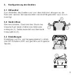
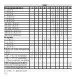
Page 11: ...er Klingenbreite von 2 5 mm benötigt 3 2 Gerät öffnen Stecker abziehen Durch leichten Druck den Verschluß auf beiden Seiten des Gehäuses entriegeln 1 Gehäuseoberteil und Elektronik herausziehen 2 3 3 Einstellungen Einstellung von Ein und Ausgangsbereich mittels des DIP Schalters SW1 und gemäß nach folgender Tabelle 1 1 2 Offset Excitation Voltage SW1 3 ...

Page 12: ... 0 0 1 50 mV 50 mV 1 0 1 0 100 mV 100 mV 1 0 1 1 200 mV 200 mV 1 1 0 0 500 mV 500 mV 1 1 0 1 Ausgang 0 10 V 0 0 0 5 V 0 1 0 20 mA 1 0 4 20 mA 1 1 Brückenversorgungsspanung 10 V 1 0 0 5 V 1 0 1 4 8 10 2 V einstellbar 0 1 0 4 8 10 2 V einstellbar 0 1 1 u Offset zusätzlich einstellbar Übertragungsverhalten Standard Ausgangssignale 0 Inverse Ausgangssignale 1 0 offen 1 geschlossen ...

Page 13: ...11 F R1 DMS R2 R4 R3 U 10 11 12 7 8 9 1 2 3 4 5 6 Versorgung Power SPS 0 5V Versorgung Messbrücke 3 4 Applikation 3 4 Applikation ...

Page 14: ...agfähigkeit der Querverbindung 2 A Klemmenbelegung 1 Brückenversorgungsspannung 2 Brückenversorgungsspannung 3 nicht belegt 4 Eingang 5 Eingang 6 nicht belegt 7 Ausgang 0 4 20 mA 8 Ausgang 0 5 10 V 9 Ausgang 0 V Bezugspotential 10 Versorgungsspannung 24 Vdc querverbunden 11 Versorgungsspannung GND querverbunden 12 nicht belegt Anschlussquerschnitt max 2 5 mm2 Mehrleiteranschluss max 1 mm2 zwei Lei...

Page 15: ...13 92 4 90 111 4 73 4 38 Querverbindungen für Spannungsversorgung GND 24 Vdc 17 5 6 Abmessungen in mm ...

Page 16: ...ndung 2 5 N 2 rot 1492 CJLJ5 2 R Querverbindung 2 5 N 2 blau 1492 CJLJ5 2 B Querverbindung 2 5 N 2 gelb 1492 CJLJ5 2 Marker Best Nr 1492 M6X10 Power Supply 24 V DC Output 15 W 1606 XLP15E 30 W 1606 XLP30E 50 W 1606 XLP50E 100 W 1606 XLP100E 120 W 5 A 1606 XLE120E DIR 10000043404 Version 00 ...

Page 17: ...lisation avec des tensions d isolement élevées veiller à avoir une distance ou une isolation suffisante par rapport aux appareils voisins et re specter la protection contre les contacts Lors du montage et des opérations de réglage du séparateur de signaux analogiques observer les mesures de protection contre les décharges électrostatiques 2 Utilisation Le séparateur analogique de signal sert à la ...

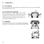
Page 18: ...Retirer les fiches Presser légèrement sur les deux languettes 1 pour déverrouiller la partie supérieure du boîtier On peut ainsi sortir la partie supérieure et l électronique jusqu à ce qu elles s enclenchent 2 3 3 Réglages Le tableau suivant donne les réglages des plages d entrée et de sortie au moyen du boîtier DIP SW1 1 1 2 Offset Excitation Voltage SW1 3 ...

Page 19: ...0 0 1 50 mV 50 mV 1 0 1 0 100 mV 100 mV 1 0 1 1 200 mV 200 mV 1 1 0 0 500 mV 500 mV 1 1 0 1 Sortie 0 10 V 0 0 0 5 V 0 1 0 20 mA 1 0 4 20 mA 1 1 Tension d alimentation du pont 10 V 1 0 0 5 V 1 0 1 4 8 10 2 V réglable 0 1 0 4 8 10 2 V réglable 0 1 1 décalage également réglable Comportement en transmission signaux de sortie standard 0 signaux de sortie inverses 1 0 ouvert 1 fermé ...

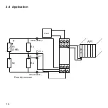
Page 20: ...18 F R1 DMS R2 R4 R3 U 10 11 12 7 8 9 1 2 3 4 5 6 Alimentation Power API 0 5V Alimentation Pont de mesure Pont Pont 3 4 Application ...

Page 21: ...r connexions transversales max 2 A Brochage 1 Tension d alimentation du pont 2 Tension d alimentation du pont 3 Non connectée 4 Entrée 5 Entrée 6 Non connectée 7 Sortie 0 4 20 mA 8 Sortie 0 5 10 V 9 Sortie 0 V masse 10 Alimentation 24 Vdc connexion transversale 11 Alimentation GND connexion transversale 12 Non connectée Section raccordement maxi 2 5 mm2 Raccordement multibrins maxi 1 mm2 deux fils...

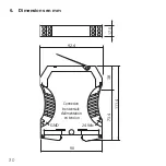
Page 22: ...20 92 4 90 111 4 73 4 38 GND 24 Vdc 17 5 Connexion transversale d alimentation en tension 6 Dimensions en mm ...

Page 23: ...sale 2 5 N 2 rouge 1492 CJLJ5 2 R Connexion transversale 2 5 N 2 bleu 1492 CJLJ5 2 B Connexion transversale 2 5 N 2 jaune 1492 CJLJ5 2 Marker Réf 1492 M6X10 Power Supply 24 V DC Output 15 W 1606 XLP15E 30 W 1606 XLP30E 50 W 1606 XLP50E 100 W 1606 XLP100E 120 W 5 A 1606 XLE120E DIR 10000043404 Version 00 ...

Reviews: