2
Rockwell Automation Publication 800G-IN005A-EN-P - May 2018
Bulletin 800G Assembled Stations
Use in areas other than those areas specified or the modification of the
product by anyone other than the manufacturer is not permitted and
exempts Rockwell Automation from liability for defects and any
further liability.
The applicable statutory rules and other binding directives that relate
to workplace safety, accident prevention, and environmental
protection must be observed.
Before you commission or restart operation, check compliance with all
applicable laws and directives.
All enclosures, front-of-panel operators, and back-of-panel modules
can be used only if they are in a clean, undamaged condition. Do not
modify these components in any way.
Standards Conformed To
Assemble, Install, and Commission
• Only qualified personnel are allowed to assemble, disassemble,
install, and commission the device.
• Protect devices against mechanical damage or electrostatic
discharge.
• Use suitable tools for installation. Do not modify the
assembled station or components in any way.
• Use cable that is rated with an appropriate temperature range
suitable for the application.
• IEC/EN 60079-17 must be observed.
Installation and Removal
Protective Earthing Components
For metal cable glands, follow these steps:
1. Position the earth plate
where the metal cable
gland is installed (top
or bottom).
2. Install the earth plate
between the rib and
inside wall of the
enclosure.
3. Open the terminal cages of the earth plate and insert the
conductors.
4. Tighten the earth plate terminals to a torque range of
0.7…1.0 N·m (6…9 lb·in).
For plastic cable glands, follow these steps:
\
1. Position the earth
bracket where the
plastic cable gland is
installed (top or
bottom).
2. Install the earth
bracket between the
rib and inside wall of
the enclosure.
3. Open the terminal cages of the earth bracket and insert the
conductors.
4. Tighten the earth bracket terminals to a torque range of
0.7…1.0 N·m (6…9 lb·in).
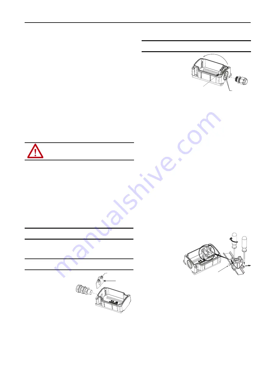
Contact Blocks and Power Modules
To install contact blocks and power modules, follow these steps:
1. Align the notch of the component with the cut-out in the
enclosure rail.
2. Snap the contact block or power module onto the rail of the
enclosure.
3. Check that the component is secured to the enclosure rail.
To remove contact blocks and power modules, follow these steps:
1. Position a screwdriver inside of the black tab at the base of the
component.
2. Gently pull the black tab in a direction away from the
enclosure rail.
3. Lift up on the component to remove it from the enclosure rail.
Wiring Contact Blocks and Power Modules
Take care when following these steps to connect cable to contact blocks
or power modules:
1. Strip 40 mm
(1.575 in.) of
sheath off the
cable.
2. Remove
approximately
6 mm (.236 in.)
of insulation
from the
conductors.
3. Prepare the ends of the fine-stranded and multi-stranded
conductors. Crimp wire end sleeves with a suitable crimp tool.
Suitable connection cross-sections are 0.75…2.5 mm2
(18…14 AWG).
4. Open terminal cage and insert conductors.
5. Tighten the terminals to a torque range of 0.4…0.7 N·m
(3.5…6.2 lb·in).
• EN 60079-0
• EN 60079-1
• EN 60079-7
• EN 60079-31
• IEC 60079-0
• IEC 60079-1
• IEC 60079-7
• IEC 60079-31
ATTENTION:
Risk of serious injury due to incorrect assembly,
installation, and commissioning.
IMPORTANT
The assembled stations that are pictured serve as an example
for all assembled station configurations.
IMPORTANT
An earth plate must be used for grounding enclosures with a
metal cable gland.
0.7…1.0 N·m
(6…9 lb·in)
Earth Plate
(800G-AEP
x
)
IMPORTANT
An earth bracket must be used for grounding enclosures with
a plastic cable gland.
0.7…1.0 N·m
(6…9 lb·in)
Earth Bracket
(800G-AEB)
0.75…2.5 mm²
(18…14 AWG)
Contact Block/Power Module
(800G-XB
x
-EX, 800G-DB
x
-EX,
and 800G-DB
x
X
x
-EX)
0.4…0.7 N·m
(4…6 lb·in)


